BTRON possesses many novel features, such as a hypertext function based on the real object/virtual object model, JIS supplemental kanji and multilingual processing functions, EnableWare (functions for the disabled), etc., but the most outstanding feature when compared with recent window systems, such as [Microsoft Corp.'s] Windows 95 and the like, is probably the point that the CPU performance and hardware resources that it requires are extremely small. For example, in order to run applications practically with the Japanese-language version of Windows 95, it is said that 32 megabytes or more of memory is required, and for the CPU also it is said an i486-100MHz or faster, if possible a Pentium, is desirable. On the other hand, the BTRON-specification "1B/V2" runs at a practical speed with just 6 megabytes of memory and an i386 at 16MHz.
Recently, due to progress in semiconductor technology and the mass production of personal computers, it has become possible to purchase personal computers equipped with a high-performance CPU and lots of memory at cheap prices. Considering that, it might seem the BTRON feature of its required hardware resources being small does not carry that much meaning. However, that is a statement that is limited to desktop computers. When we expand the range of computers subject [to discussion] and consider, for example, small-scale notebook personal computers, personal digital assistants (PDAs), and mobile uses, it is after all difficult to possess abundant hardware resources, and when the performance of the CPU becomes higher, electrical consumption increases and battery life becomes shorter. An OS to be used in this type of computer, needless to say, has to be one that is compact. On this point, BTRON is vastly superior to Windows 95. In particular, with BTRON, because it is possible to run the OS practically even though the CPU's performance is low, it is possible to lower the electrical consumption by holding down the clock speed, and [as a result] there is a multiplier effect in which it is possible to make the batteries lighter while lengthening the duration time for the batteries.
However, the BTRON specification itself is originally an OS specification for use on personal computers and workstations; it does not include specifications for such things as power management functions, which are required in PDAs. Therefore, we added a power management function and a human/machine interface (HMI) that does not require a keyboard to the BTRON specification (to be exact, the BTRON3 Specification), and thus the micro-BTRON specification was designed as revamped OS specification for PDAs. Since we at Personal Media Corp. were able to develop together with Seiko Instruments Inc. the "B-right" OS based on this micro-BTRON specification and implement it on a PDA called "BrainPad TiPO," I will give a summary of this in this paper.
As was mentioned in the previous section, the BTRON that was revamped for PDAs is micro-BTRON. In concrete terms, there were such alterations as modification of the HMI specification in order to make possible operation even with hardware having a small screen and no keyboard, modification of the OS specification in order to realize that, and addition of a power management function.
At Personal Media, we designed assuming the following hardware specification with the micro-BTRON-specification OS "B-right" that we implemented.
For the pointing device [PD] for "B-right" we made it possible to employ a pressure sensitive electronic pen and also a touch panel. Specifically, we made it possible to employ a one-button PD, and not just the two-button electronic pen or mouse, as is assumed in the BTRON specification. In this case, it is desirable to provide for a switch or a key on the machine's main unit or keyboard to serve as a substitute for the menu button, but instead of making this a mandatory requirement, we made it possible to operate even with a machine that does not have a menu button.
In the case of a pressure sensitive electronic pen or touch panel, a physical switch is not attached to the tip of the pen in the manner of the electronic pen for the TRON-specification keyboard; instead, it is necessary to use data as to whether or not an electronic pen or a [person's] finger has contacted the screen. In this case, we decided to realize the BTRON-specification HMI by regarding an electronic pen or a [person's] finger that has contacted the screen as the pressing of the main button.
Furthermore, we decided not question whether or not the tablet for the electronic pen is in the body of the screen. In other words, we made it possible to implement "B-right" either in hardware in which the tablet is unified with the screen or in hardware in which it is separated [from the screen].
We made it possible to implement "B-right" even on a machine to which a physical keyboard is not connected. In a case when there is no keyboard, we decided to accomplish key input through pointing with the PD at the key tops of a software keyboard accessory (keyboard emulator) displayed on the screen. In addition, we also made it possible to carry out handwriting recognition and send those results to the application instead of key input.
We made it possible to operate "B-right" even with a small screen so that it would be possible to install it even on PDAs with outstanding portability. Specifically, it is possible to install it even with screens down to the range of 640 x 200 dots or 320 x 240 dots, and we designed screens matched to these. Also, the screen can either be color or black and white.
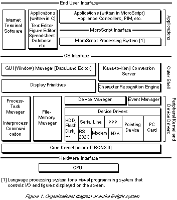
In the micro-BTRON-specification OS "B-right," we employed a microkernel-type internal organization with the aim of real-time responsiveness and improving maintainability and expandability. Specifically, we first divided the OS into three layers: a core kernel, a peripheral kernel, and an outer shell; and for the core kernel, we decided on a subset of micro-ITRON3.0 (there are also some functions that have been added) (Fig. 1). The core kernel manages the layers from the peripheral kernel and above plus the basic resources of such things as tasks and memory that we use with device drivers. At the peripheral kernel layer, we manage the various resources and functions that micro-BTRON applications use, such as files, devices, processes, events, etc. At the outer shell level, we manage functions related to the graphical user interface (GUI), such as the graphics functions, window system, kana-to-kanji conversion, etc. The functions of the peripheral kernel and outer shell are realized through independent managers by responding to the objects of those operations. The managers are embodied in a group of tasks that run below the core kernel; for example, we realize processing of page-out and page-in (in the case the CPU supports virtual memory), the processing of file management overall, etc., through separate tasks. Moreover, the device drivers are also embodied in a group of tasks that operate above the core kernel. In this manner, through a method in which we realized not with the kernel but with tasks a portion of the functions that the OS possesses plus device drivers, the inside of the OS was modularized and maintainability and expandability were improved. In addition, it becomes easy to receive interrupts even though the OS (peripheral kernel and outer shell) is executing, which made it possible to also raise responsiveness.
Also, by adopting the microkernel method and modularizing the inside of the OS based on that, it became possible to carry out the proper use of ROM and RAM in small units. In PDAs, because we use low-cost mask ROM in large amounts, it is necessary to burn into ROM the object code of the OS and applications as far as possible. However, there are cases in which it is impossible to avoid fine modifications of specifications and version upgrades after the ROM has been manufactured. In order to satisfy this demand in "B-right," for programs that have been burnt into ROM, we created a function that carries out patching with module units (function units, such as task management, synchronized communications, etc.), which are switched into programs in RAM.
Next, I will explain the HMI in the micro-BTRON-specification OS "B-right." The HMI of micro-BTRON is basically the same as the BTRON HMI, but the following modifications were carried out so that it could operate even on a machine that had no physical keyboard or with a one-button -type PD (a PD without a menu button).
Because we assume that the micro-BTRON OS will be installed in a mobile machine, there will be many cases in which it will not be possible to connect a physical keyboard. As a means for key input in such cases, we have provided a software keyboard accessory function. A software keyboard accessory is software for the purpose of carrying out key input through which we display the picture of a keyboard on the screen and click the keys inside it with a PD. In the software keyboard, the screen changes in response to input modes such as alphanumeric, Japanese kana, etc. That state is shown in Fig. 2.
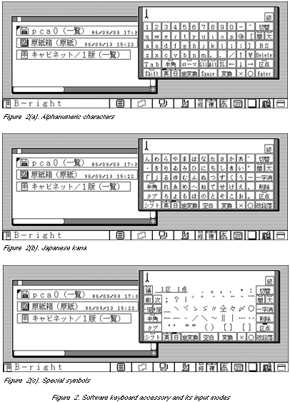
In kana-to-kanji conversion in the BTRON specification, in order to lessen the movement of the user's eyes, the HMI is made to display the candidates for character conversion in the location where the characters are to be input (the caret location of the basic text editor, etc.). However, in a case when we are utilizing the software keyboard accessory, the user's eyes cannot but be fixed on the window of the software keyboard rather than the application. As a result, there is less of a burden on the user by the carrying out kana-to-kanji conversion also inside the software keyboard. For that reason, we made up the specification so that kana-to-kanji conversion also is carried out inside the software keyboard accessory.
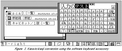
In addition, because kana key input and kana-to-kanji conversion are carried out inside the software keyboard accessory, it is necessary to be able to carry out operation using the PD also for selecting the next candidate and previous candidate [for character conversion], moving the concerned phrase, etc. This state is shown in Fig. 3.
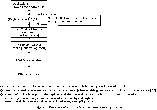
The software keyboard accessory converts the user's PD operations into key events and supplies them to the application at a level that is closer to the hardware than the application. In order to realize this function, we implemented the software keyboard accessory using the micro-BTRON-specification front window function and front-end process.
The front window is a window that is placed even further to the front than the active window (the window that receives input at the very front), and it is a window that is used for the purpose of supporting the operations of the active window. Interactive operations from the user are always sent to the active window via the front window. Moreover, the front-end process is a process that carries out preprocessing of events and so on by intercepting that the events that the active process (the process that manages the active window) normally picks up. By utilizing these functions in the software keyboard accessory, we made it possible to convert a PD-related event such as PD button down (EV_BUTDWN) into a keyboard [KB]-related event such as key down (EV_KEYDWN), and then passed along to the application. This state is shown in Fig. 4.
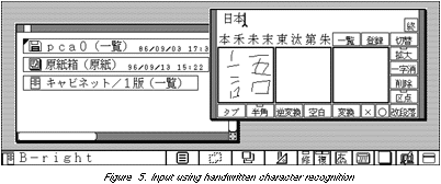
It is also possible to incorporate a handwritten character recognition function in the software keyboard accessory (Fig. 5). Both in the case of performing kana-to-kanji conversion and in the case of performing handwritten character recognition with the software keyboard accessory, the character code of the kana-kanji mixed script that is output as a result is passed over to the application. Consequently, it is possible to carry out processing on the application side without being aware of the input method for those character codes--in other words, whether they come from a physical keyboard, whether they come from the software keyboard accessory, or whether they come from handwritten character recognition.
Because there are many cases with mobile machines in which the screen size is small, it is necessary to realize an HMI that is efficient with small screens. The screen and windows in the BTRON specification are originally of a simple design, but in the micro-BTRON specification we redesigned the entire screen image so that the necessary operations could be carried out even with small screens on the order of 640 x 200 dots or 320 x 240 dots.
As for the specific points that were modified, first in order to expand the vertical dimension of the workspace on the screen, we eliminated the title bar at the top of windows. In its place, we made it so that the pictogram and the selected real object name that is displayed in the title bar of the windows in the BTRON specification are displayed in a system message panel in the bottom left-hand corner of the screen. Also, by making the frame on either side of the window thicker, we made provisions so that the title bar or the window frame would not become difficult to grasp when moving windows.
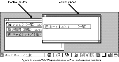
The difference in status as to whether a window is active (the status to receive input at the very front) or inactive is expressed through differences in the patterns and shading of the frame in the same manner as the windows in the BTRON specification. In Fig. 6, we show the differences between active and inactive windows. Furthermore, pictograms and selected real object names are not displayed for inactive windows.
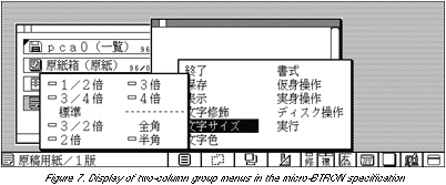
Next, we created a function that displays menu items by making them into two-column and three-column groups so as to make possible menu display and operation even though the height of the screen overall is low. Because there was no function for two-column menus in the BTRON specification, it was specified that menu contents are to be scrolled in cases when there are lots of menu items and all these items cannot be displayed vertically. However, because this specification is difficult to use with touch panels, in the case of the micro-BTRON specification, we specified that menu items are not to be scrolled, rather menu items are be displayed and operated by making them into two-column an three-column groups (Fig. 7). Two columns for menu items is possible both for the basic menu and the child menu.
Also, in order to adjust and reduce menu items, the "window" and "accessory" menus, which were in the joint menu in the BTRON specification, were modified so that they could be directly selected from the system message panel at the bottom of the screen, and they were deleted from the joint menu. Furthermore, in order to make it possible to utilize even a one-button-type PD, we created a software switch on the system message panel to take the place of the menu button.
In the micro-BTRON specification, in order to avoid hardware limitations such as there being no keyboard or no menu button on the PD, we realized on the screen various kinds of software switch types that make possible operation with a PD. We specified that these switch types are to be collected and laid out on the right side of the system message panel at the bottom of the screen (Fig. 8).
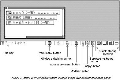
As for the switch types that are placed in the system message panel, from the left in order, we provided the main menu button, window switching button, accessory menu button, modifier switch, copy switch, software keyboard button, and quick startup buttons. In addition these, at the left end of the system message panel, the active window pictogram (called the application pictogram) and the title are displayed. The functions of the respective buttons and switches are as follows:
We created the "main menu button" as a button for displaying and making selections [within] the main menu. By clicking on this button, the main menu appears and attains a status in which one can select [within] the menu. This is a function for performing menu operations with a one-button-type PD. Furthermore, the "accessory" menu and "window" menu that were in the main menu of the BTRON specification were removed from the main menu in the micro-BTRON specification in order to make it possible to substitute them with the window switching button and the accessory menu button.
We created a "window switching button" function as a switch for switching the active window. When this button is clicked, a summary of the windows currently being displayed is displayed as a menu. By selecting an arbitrary item among those, that window is switched to active. In the BTRON specification, there is a window menu inside the main menu, and the specification was made up so that a function corresponding to this was realized from inside that, but in the micro-BTRON specification we modified this to specify that the operation would be carried out with an independent button.
Furthermore, if a portion of the window can be seen on the screen, it is possible to activate that window by clicking the portion that can be seen. This is the same for both BTRON and micro-BTRON. What it is necessary to use a window switching button function for are cases in which the window one wants to activate is hidden by another window and cannot be seen at all.
In the micro-BTRON specification, it was expected that when multiple windows are open there would be many cases in which windows overlap and become completely hidden due to the hardware screen used for execution being small. However, if one uses the window switching button, it is possible to easily carry out the window switching operation even in cases like that.
We created the "accessory menu button" as a button for displaying and making selections from the accessory menu. By clicking on this button, the accessory menu appears and turns to a status in which it is possible to select accessories that are to be started up.
We created a "modifier switch" as a button for realizing the status of the shift key pushed down in machines to which a physical keyboard cannot be connected. It is initially in the OFF status, but if one clicks on this switch, it turns to ON status, and if one clicks it once more, it returns to OFF status. While this switch is in ON status, it is regarded as the status in which the shift key has been pushed; for example, a selection operation with the PD becomes a modified selection.
Furthermore, that which we call a modified selection in the BTRON specification or the micro-BTRON specification means an operation carried out to add or delete an object (text, figure, virtual object, etc.) that is in selected status, and it is realized by pressing the PD while pushing down on the shift key or with the modifier key in ON status. Conversely, pressing the PD in normal status (status in which the shift key is not pushed down, or status in which the modifier switch is OFF) means a new selection operation. In this case, the selection status of the object that had been selected up to that point is canceled, and a new object is selected.
We created a "copy switch" as a switch for switching between whether an object is to be moved or copied when dragging an object in selected status with a PD.
In the case of the BTRON specification, it was specified that switching between whether an object is to be moved or copied is to be performed with the menu button of the PD. However, in the case of the micro-BTRON specification, because there cannot be a limitation stating that the PD menu button can be utilized, we adopted a policy of substituting for that function with this "copy switch."
The copy switch takes three statuses: OFF status, sticky shift status, simple lock status. The initial value is OFF status, and a dragging operation becomes a moving operation. When the copy switch is clicked in OFF status, it turns to sticky shift status, and the next dragging operation becomes a copying operation. However, once we carry out a drag operation in sticky shift status, the copy switch returns to OFF status. For that reason, dragging operations from the second time onward return to moving operations. On the other hand, when we double click the copy switch in OFF status, it turns to simple lock status, and all dragging operations from the next onward become copy operations. When we single click or double click the copy switch in simple lock status, it returns to OFF status, and dragging operations after that also return to moving operations.
Moreover, the names "sticky shift status" and "simple lock status" are ones that are modeled on the same functions included in EnableWare functions (functions for the disabled) in the BTRON specification.
We created the "software keyboard button" function as a button for starting up the software keyboard accessory. Because the frequency of use of the software keyboard accessory is high, we improved operability by creating a startup button exclusively for this use.
We created the "quick startup buttons" as a switch group for starting up accessories with a simple operation. Multiple pictograms representing accessories (called accessory pictograms) that are to be started up from here are laid out next to each other, and by clicking the accessory pictogram it is possible to start up the corresponding accessory with one touch. When one clicks this button when a corresponding button has already been started up, the window of that accessory becomes active.
There are limitations on the number of accessory pictograms that can be laid out as quick startup buttons due to the screen size restrictions of the system message panel. For that reason, accessories that can be started up from the quick startup buttons are limited. In actuality, we made it so that it would be possible to start up from the quick startup buttons accessories with a high frequency of use that are important in running the system, for example, the accessory that manages the battery information and the accessory that changes the contrast of the liquid crystal display. Furthermore, accessories outside of these can be started up from the accessory menu button mentioned above.
Moreover, modifications of the HMI of the type explained in this section are realized through the outer shell in the micro-BTRON-specification OS "B-right," and in principle do not influence applications. Thus it is possible to have commonality between applications that run on top of the micro-BTRON-specification OS, in other words, applications executed with a machine having no physical keyboard or menu button on the PD, and applications that run on top of a BTRON-specification OS, in other words, applications that are executed on a machine to which a keyboard and a mouse is attached.
In PDAs, various types of power management functions are demanded in order to extend the battery duration time. For power management functions, there are ones that are realized with hardware, but there are cases in which it is necessary to deal with this also at other level, such as the OS, device driver, and application [levels]. For this reason, in the micro-BTRON-specification OS, we implemented various power management functions of the types that will be explained below.
In addition, in the micro-BTRON specification, switching over to power OFF status from normal operational status while preserving data for the resumption of execution is called SUSPEND, and the status after SUSPEND is called the SUSPEND status. Also, moving from power OFF status to power ON status and resuming execution of the OS and applications that were suspended is called RESUME. In the ITRON specification also the terms SUSPEND and RESUME are used for task status transition, but the meaning is different from this.
As the causes of the SUSPEND that are supported in the micro-BTRON specification, there are such things as power switch operation, unlocking of the battery cover, undercharged batteries, and automatic power off when there is no operation by the user. Also, as causes of the RESUME function, there are such things as power switch operation, elapsing of time based on a timer, and telephone arrival signal from a serial line or PC modem card.
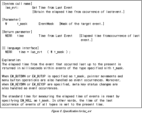
If there has been no operation by the user during a fixed period of time, the power is automatically set to OFF to conserve power. This function is called "automatic power off." In the micro-BTRON specification in order to efficiently perform monitoring of user operations, we added a system call (las_evt) that knows an event that occurred in the past. This system call possesses a function to return the elapsed time from when a type event specified with parameters last occurred until the present (Fig. 9).
In the micro-BTRON-specification "B-right," we made it so that a system demon would use las_evt and then perform automatic power off processing. The system demon, after entering a wait status for a fixed period of time, investigates the state of events that occurred in the past using las_evt. Depending on the results of las_evt, if the demon discerns that an event caused by a user operation has not occurred within a fixed period of time, it carries out automatic power off processing. On the other hand, if an event caused by a user operation has occurred, (if the user is operating the machine) the demon enters wait status and repeats the process in which las_evt is executed without performing automatic power off processing.
In cases where there has been a device access request from an application, the file manager, etc., in the micro-BTRON-specification OS, the device manager of the OS's peripheral nucleus calls up the device driver. Device drivers run as independent tasks above the core kernel, and they process the types of commands in Fig. 10, which are put out by the device manager.
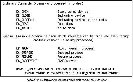
Among the commands in Fig. 10, the ones that were created to realize power management functions in the micro-BTRON-specification OS are DC_SUSPEND and DC_RESUME. When the system carries out SUSPEND, the device manager of the OS peripheral kernel sends out the DC_SUSPEND command for the device driver that is processing at that time. Moreover, when the system carries out RESUME, the device manager of the OS peripheral kernel sends out the DC_RESUME command for the device driver to which the DC_SUSPEND command had been sent. The contents the device driver is to process for these two commands are as follows:
(1) If there is a command currently being processed, the device driver either waits until it is completed, or it suspends or stops it. Temporarily interrupting a process inside a device driver and then continuing it after RESUME is "suspension," and completely ending processing in the manner of DC_ABORT is "stopping." In the case of "stopping," since an error returns to the source of the request (application, etc.), the source of the request generally re-executes device access after RESUME. Which of these methods, "completion of processing," "suspension," or "stopping," should be selected depends on the implementation of the device driver. However, in a case when there is the possibility of entering into a long wait, the device driver has to either suspend or stop without waiting for the processing to reach completion. This is for the purpose of processing without delay a highly urgent cause for SUSPEND, such as insufficient battery power. Also, because "stopping" has serious effects on an application, it should be avoided to the utmost.
(2) The device driver suspends receipt of new commands outside of DC_RESUME.
(3) The device driver carries out hardware suspend processing as necessary.
(1) The device driver carries out hardware resume processing as necessary.
(2) The device driver resumes receipt of normal commands.
By supporting DC_SUSPEND and DC_RESUME in the micro-BTRON-specification OS "B-right" and its device drivers, we made it possible to implement SUSPEND and RESUME processing that is conforms to the characteristics of each device driver.
Processing at the time of SUSPEND and RESUME, as a rule, is closed off inside the hardware, device driver, and OS, and does not influence the application. In other words, even if there is a SUSPEND and after that a RESUME through power ON during the execution of a program, because the hardware, device driver, and the OS perform all the necessary processing for that, it is not necessary for the application to process anything. When looked at from the application, it should appear so that nothing proceeded during the SUSPEND state and then only the time suddenly moved forward at the time of RESUME; in general, there is no inconvenience as a result of this, and it is also not necessary for the application to know that the system entered SUSPEND status status during processing.
However, in a case when the environment for using the machine changes after RESUME, there are also cases when the need occurs for the application to respond to this. For example, the following instances can be imagined.
With an application that uses modem-based communications or a LAN, there is the case in which the system cuts the circuit, and then at the time of RESUME performs processing to connect again (or reconfirms the connection).
With an application that is used after inputting of a password, there is the case in which the system will force reentry of the password, assuming the possibility that the user had changed after RESUME.
In order to realize functions of this type in the micro-BTRON-specification, we created a function that notifies an application of SUSPEND and RESUME. However, this notification is not something that is performed for all processes and applications, rather we made it something that is performed only for those applications that require this. As for the concrete specification of the SUSPEND notification function, we made it as follows, and we implemented it to process this by means of the previously mentioned system demon.
(1) Registering a request to notify of SUSPEND
In a case when the application makes necessary notification at the time of SUSPEND or RESUME, it sends a message to the system demon and registers that request. Furthermore, in obtaining the process ID of the system demon, the application uses the function for global name management. Even when registration is canceled, the application sends a message of that purport to the system demon.
(2) Notification of SUSPEND to the application
When some reason or other for SUSPEND occurs and the system attempts to SUSPEND, a message indicating switching over to SUSPEND is transmitted to the application that has registered with the system demon by means of (1).
It is necessary for the application that has received a message notifying of SUSPEND to return a reply message that processing has ended to the system demon after performing the necessary processing for that. The system demon delays SUSPEND for the entire system until it has received reply messages for all the notifications of SUSPEND. By means of this function, we made it possible to guarantee execution of the necessary processes on the application side at the time of SUSPEND. However, because the time of SUSPEND for the entire system is prolonged when the response from the application is delayed, caution is required in a case when the cause of SUSPEND is highly urgent, such as insufficient battery power.
(3) Notifying of RESUME to the application
Immediately after the system processes RESUME also, a message indicating RESUME is sent to the application that has been registered with the system by means of (1). A response from the application for the RESUME notification is not required.
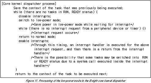
In order to decrease electrical power consumption as much as possible during operation with the micro-BTRON-specification OS "B-right," we created a function that puts to use the low power consumption mode that is supported in the hardware. Specifically, when there is nothing left to be executed by the tasks the core kernel manages (when there are no tasks left in RUN or READY status), we made it so that the operating system switches into the low electrical power consumption mode (the low power consumption mode that the CPU supports or the mode in which the operating clock frequency of the CPU is lowered), which has been prepared in hardware. In the case of "BrainPad TiPO" that we implemented "B-right" at this time, because the CPU has a function to lower the CPU clock to 32KHz and hold down electrical power consumption, we decided to put this to use as the low electrical power consumption mode. Incidentally, the CPU clock during normal operation is 18MHz or 9MHz.
We made it so that switching over to and returning from low electrical power consumption mode is processed inside the core kernel dispatcher. The specific algorithm for this is shown in Fig. 11. In the case of "BrainPad TiPO," there is a problem in that it becomes impossible to access DRAM in the low electrical power consumption mode in which the clock in lowered to 32KHz (the contents of the DRAM are preserved). For that reason, programs that are to be executed in low electrical power consumption mode, are not placed in DRAM, rather we devised the scheme of putting them in ROM or SRAM.
Moreover, for the electrical power consumption reduction function to operate efficiently during idle, applications and the OS have to perform a regular polling process (busy loop). In other words, when the processes and tasks that make up the OS peripheral kernel and outer shell and the applications are waiting for the change in some status, it must be made so that they definitely use wait statuses (the WAIT and SUSPEND statuses of the micro-ITRON specification). In order to satisfy this condition, we used an implementation method different from that of the BTRON-specification for the event loop processing part of the outer shell, the selection frame (flickering frame) and the flashing display portion of the caret, the parts manager, and some applications.
The micro-BTRON-specification OS "B-right" was implemented on the Seiko Instruments Inc. PDA called BrainPad TiPO, and is already running. The hardware specification for BrainPad TiPO is shown in Table 1. (For external views of BrainPad TiPO, please see TiPO Gallery.)
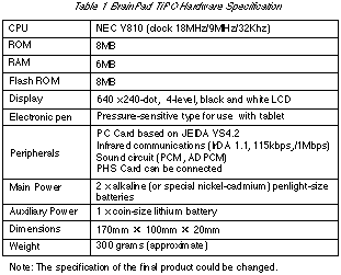
The CPU used in BrainPad TiPO is an NEC V810 with a domestically produced architecture. The merits of this CPU are that it has an extremely small power consumption of 10mW per MIPS, and that it also possesses a low electrical power consumption mode that operates with a clock of 32KHz, and thus it was judged that it is suitable for mobile use, such as a PDA. However, because this CPU does not have a memory management unit (MMU), it was necessary to revamp the file memory manager portion of the OS outer shell in porting B-right.
The B-right OS itself (core kernel, peripheral kernel, outer shell) and the majority of the system applications (basic editors, communications software, etc.) plus the kana-to-kanji conversion dictionary and fonts are burnt into mask ROM, which is useful in saving RAM and shortening programming loading times. In addition, mask ROM has an advantage in that it can be supplied at low cost.
Flash ROM in BrainPad TiPO are put to use as a secondary memory device, and they are used for the purpose of storing programs that were not entered into mask ROM, versions of programs that were upgraded after the mask ROM was burnt, and data prepared by the user. When the capacity of the flash ROM is insufficient for entering user data, it is possible to use a secondary memory device based on a PC card (a 20 to 40 megabyte ATA flash memory card, etc.).
For the main batteries, we use two penlight alkali dry cells, which are low cost and easy to obtain. At present, we are in the process of fine tuning and evaluating electrical power consumption and battery duration time, and although the final figures have not appeared, we are aiming at a battery duration time of 40 to 60 hours. Even if this machine is used two hours per day, it figures that the batteries will last approximately for a period of one month. In contrast to this, the duration time of the lithium ion batteries in a PC/AT-compatible notebook with Windows 95 installed is normally two to three hours, and on the order of five to six hours at the longest. From the aspects of electrical power consumption and mobility, I believe that everyone will accept that BrainPad TiPO with the micro-BTRON-specification OS installed is far and away superior.
Because a PDA manages important data for individuals, such as schedules and so on, data loss resulting from hardware and battery troubles has to be prevented as far as possible. For that reason, BrainPad TiPO has, in addition to the main batteries that are normally used, an auxiliary battery that is used to back up memory when changing the main batteries. In addition, BrainPad TiPO is also equipped with a function that suspends the entire system by issuing an interrupt as a result of the battery cover being opened.
Next, I shall report on the amount of memory required for the micro-BTRON-specification OS "B-right." First, from the object code of each module in "B-right," we calculated the theoretical values for the ROM size (object code) and RAM size (data portions) required for execution, which resulted in Table 2. Second, we actually measured the amount of memory (including that burnt into ROM, such as for fonts) that is used from system startup until the stage when the initial window is displayed, which came to 3,362 kilobytes. This value is almost the same as 3,662 kilobytes that is the sum total of the ROM capacity and RAM capacity of the "total of 1 through 5" in Table 2, which substantiates the fact that the theoretical values of Table 2 roughly accurate.
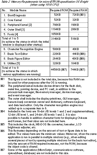
Among these, the RAM required by applications such as the basic text editor and the basic figure editor fluctuates according to the data that is handled. Table 2 is required RAM capacity when data selected for editing is empty, and depending on the data to be handled, the required RAM capacity increases. However, in a case when there are multiple of these applications open, only the RAM capacity required for data use increases, because the object code is shared. We are still in the process of evaluating required memory capacities for applications outside of these, such as communications software and MicroScript, but we expect the required memory capacities will be to the same extent as the basic text editor and the basic text editor.
As a result of taking into consideration applications that will be added in the future and including them with the the figures in Table 2, we calculated that the amount of memory required for the micro-BTRON-specification OS "B-right" is 6 megabytes of ROM and 2 megabytes of RAM in the minimal configuration, and 6 megabytes of ROM and 4 megabytes of RAM for practical use. With just this much memory, it is possible to open 10 or more of windows of the various applications and operate the machine practically. BrainPad TiPO, needless to say, satisfies this specification. Moreover, with just this much ROM, the secondary memory device, such as the flash disk, can be utilized entirely for entering the user's data, since the applications, fonts, and so on, can all be placed in ROM. Conversely, if there is room to put the application object code and fonts in the secondary memory device, it is possible to decrease the ROM capacity.
Furthermore, because the CPU used this time is a RISC-type NEC V810, the object code size is greater than that for a CISC-type CPU. If another CPU is used, we can expect that the amount of required memory (mainly ROM capacity) will further decrease. Also, if the system is fine tuned for a particular use and the unnecessary functions are removed (for example, kana-to-kanji conversion), it is possible to operate the system with an even smaller memory.
Although BrainPad TiPO with micro-BTRON-specification OS "B-right" installed is small, it is a system that completely satisfies the BTRON (for the HMI, micro-BTRON) specification, and it holds within itself the possibility of further development in cooperation with the BTRON-specification OSs developed to date, "1B" and "3B." In this section, I shall explain the relationship between BrainPad TiPO and 1B and 3B.
The file format for B-right is based on the BTRON specification. It is not possible to use floppy disks with BrainPad TiPO, but it is possible to utilize PC cards such as ATA flash cards (hard disk cards), as removable media, and hence it is possible to carry out data exchange with a 1B notebook personal computer via the the PC card. The method for the operation is exactly the same as when using a floppy disk with 1B. For example, when transferring data from a 1B notebook personal computer to BrainPad TiPO, the procedure is as follows:
(1) Insert the ATA flash card into the 1B notebook personal computer. Since the device virtual object will appear when that is done, open that into a window. (Fig. 12[a])
Note: It is necessary to use the latest version of 1B, 1B/V3, in order to handle ATA flash cards and multiple languages.
(2) Copy the real object that is to be the object transfer into the ATA card window (it is all right even if this forms a real object/virtual object network). The real object that is the object of the transfer is is copied onto the ATA flash card through this operation. (Fig. 12[b])
(3) Take out the ATA flash card and insert it into the BrainPad TiPO that is the transfer destination. Since the device virtual object will appear in the same manner as just mentioned, open that into a window. (Fig. 12[c])
(4) Since the real object that is to be the object of the transfer is displayed inside ATA flash card window, copy the real object into the appropriate window on BrainPad TiPO. (Fig. 12[d])
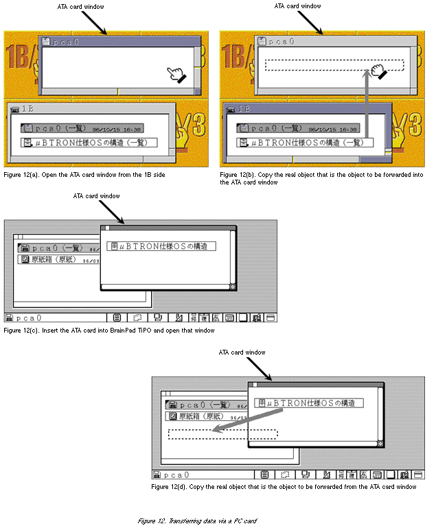
Transfer in the reverse direction also is possible using the same operation. Moreover, the contents of the B-right file are the same as BTRON and are in TAD format, hence it is possible to freely exchange between BrainPad TiPO and a 1B personal computer document data in which text, figures, and tables are mixed together. Furthermore, the multilingual functions implemented in 1B/V3 are also supported, and thus it is possible to handle the mixing together of Japanese with Chinese and Korean characters also.
With B-right communication software it is possible to also utilize the same TAD communication functions as 1B and 3B. What we call TAD communication functions are functions that enable us to transmit and receive in real time data in which we have mixed characters with figures and embellishments attached (underlined characters, enlarged characters, etc.) among ordinary characters. In other words, if we connect BrainPad TiPO and a 1B personal computer or a 3B workstation via a modem or serial line, it is possible to also carry out the transmission of figures through the medium of communications software.
Concerning programs, there is no compatibility for applications written in C language because the CPUs are different. However, MicroScript, which runs on 1B and 3B, has been implemented on B-right also, and thus there is compatibility for applications written in MicroScript. Incidentally, for those who do not know about it, MicroScript is a visual programming system on BTRON that can freely operate such things as figures (graphics), virtual objects (icons), windows, input/output, etc. By utilizing MicroScript, one can easily carry out development of programs, including the HMI. Furthermore, the MicroScript implemented on B-right has more powerful functions than the MicroScript running on 1B and 3B.
In addition, spreadsheet software and database software (MicroCard) running on 1B and 3B have already been ported to B-right, and thus it is possible to use them on B-right also. Moreover, it is also possible to run Internet-related software, such as a WWW browser and PIM software that manages personal data.
In this manner, the data compatibility between B-right or BrainPad TiPO and 1B and 3B is extremely high. As a result, it is possible to use, for example, a 1B personal computer in the office or at home, and then when going out, transfer only the necessary data to BrainPad TiPO and carry it along. It seems like a new style of use will open up in the future based on cooperation between the two.
Recently, the value of utilizing PDAs that can be employed as easily as a handheld calculator has been steadily rising due to the consolidation of the communications environment, which is to say, the spread of the Internet and mobile telephony. However, there is a broad array of functions that are required in PDAs, such as the sending/receiving of e-mail, the editing/management of e-mail, a WWW browser, the preparation of documents with pictures inserted in them, a database, schedule management; moreover, outstanding operability is also required. It is difficult to realize these processes in an environment without an OS (i.e., with dedicated software), and there are problems also from the point of extensibility, which is to say, adding applications and the like. On the other hand, because an OS for PCs such as Windows 95 requires a high performance CPU and considerable hardware resources, it is not adaptable to PDA or mobile uses. In constructing a general-purpose and practical window system on a PDA with many limitations in the areas of hardware resources and battery capacity, it is necessary to utilize a compact, high-performance OS that is easy to burn into ROM and fine tune.
At Personal Media, by revamping the BTRON-specification OS for PDAs, we succeeded in developing the micro-BTRON-specification OS "B-right" that satisfies these conditions. The amount of memory "B-right" requires, in other words, the figures of 6 megabytes of ROM and 4 megabytes of RAM, is something that sufficiently satisfies the hardware conditions that make it possible to realize a PDA.
By means of the micro-BTRON-specification OS "B-right," we actually proved it is possible to construct a practical window system even on a PDA with many hardware limitations.
BrainPad TiPO on which we implemented B-right was officially announced prior to the Mobile Computing Exhibition that was held from October 23, 1996, and it drew a great deal of attention. In addition to Seiko Instruments Inc. marketing this PDA for enterprises and OEM customers, Personal Media plans to market it to the general public under the product name of "Denboogu, or Electronic Stationery." We would be most pleased if you contacted the address listed below for inquiries concerning the detailed specification, price, and way to obtain "Denboogu." Furthermore, in this paper, I described an OS under development, so I would like to warn in advance that there is also the possibility the specification could change for the "Denboogu" that will actually be marketed.
I would like to express my thanks to Prof. Ken Sakamura of the University of Tokyo who gave me continuous guidance while writing this paper. I would also like to express my thanks to Seiko Instruments Inc. for their cooperation in studying the "B-right" specification and implementing it in hardware.
For further information on micro-BTRON-specification OS "B-right" and "Denboogu," please contact:
E-mail: spd@personal-media.co.jp
http://www.personal-media.co.jp
The above is the translation of a special report on the development of the B-right operating system for PDAs that appeared on pages 15-29 in vol. 42 of TRONWARE, which was translated and loaded on this web page with the permission of Personal Media Corporation.
Copyright © 1996 Personal Media Corporation
Copyright © 1997 Sakamura Laboratory, University Museum, University of Tokyo