Personal Media Corporation likes to market MicroScript as a "visual programming language," but, as we have seen in the previous two chapters, it can also be used to process numbers, characters, and text. So why the emphasis on the visual? That's because, from the point of view of a professional programmer, it is best suited to building interfaces, something that takes up a considerable amount of time when done using C language. Using MicroScript, on the other hand, the programmer can actually farm out the art work to a computer graphics artist, since the program source code and the figures it manipulates are two independent things. Thus, for example, while the computer graphics artist is creating high quality buttons, the programmer can be moving along writing and debugging source code using not so pretty temporary buttons that can easily be swapped for new ones in a matter of seconds as long as they are the same size.
Of course, ordinary folks can also benefit from MicroScript's visual programming capabilities. Even a person with little experience in computer programming can easily learn how to create an effective presentation in which various types of visual effects are employed, all the way up to and including animations. People who have previously used software products such Apple Computer Inc.'s HyperCard software will have no problem wrapping their minds around what MicroScript can be used for. Moreover, since MicroScript is built on top of a hypertext file system, as was HyperCard, and because it is part of the Cho Kanji operating system that comes standard equipped with word processor, spreadsheet, and card database applications, files from business productivity applications anywhere in the system can easily be incorporated into those presentations merely by creating a link to them. No copying and pasting of files is necessary.
In this chapter, we are going to present the basics of creating and manipulating graphics in the BTRON environment using the Basic Figure Editor and MicroScript, and we will even create a control interface that incorporates buttons. This can easily be created even by beginners. At the bottom of this chapter, as usual, we will present some sample scripts for advanced programmers. These are taken from the samples collection bundled with the Cho Kanji operating system package. Prior to reading this chapter, we suggest that you first read the article "A Taste of MicroScript," which can be found here. This article shows how to move a square around the screen. Interestingly, after this small snippet of MicroScript code was released on the Web, there were people praising MicroScript as an excellent shell scripting language. Yes, it really is.
In the world of BTRON, graphics, images, and the like are all called "figures," and thus the software application that creates and manipulates these figures is called the Basic Figure Editor. BTRON specifications call for both a Basic Text Editor and a Basic Figure Editor as standard equipment, and both of these are used as parts of the MicroScript programming and execution environment.
Figures created on top of BTRON will be in the TRON Application Databus (TAD) format, but it is also possible to import three types of non-native graphics files from other operating systems. These are:
Accordingly, if you are in a hurry and don't have time to learn how to use the Basic Figure Editor, you can use your favorite graphics program on another operating system to create interface parts, and then download them in one of the above file formats to BTRON or PMC T-Shell for incorporation into your MicroScript program. For those who are curious and/or have the time to learn how to use the Basic Figure Editor, we offer the following brief explanation of how the basic tools of the Basic Figure Editor work.
To someone who has never used BTRON before but is familiar with the history of computers, the best way to describe the Basic Figure Editor is to say that it incorporates the basic capabilities of Apple Computer Inc.'s MacDraw, MacPaint, and MacWrite, three killer applications that helped make the Macintosh personal computer a success. In technical parlance, we say that it can create and handle vector graphics, raster (bitmap) graphics, and text processing (both horizontally and vertically). However, in addition to images, virtual objects that link to real objects can also be incorporated into MicroScript real objects, which are what we call files in the BTRON architecture.
 |
|
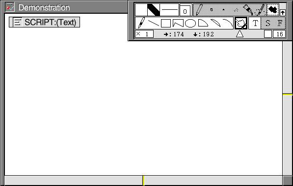
Above in Fig. 1, we see a newly created MicroScript real object, which is essentially a Basic Figure Editor real object, or graphics file. As one can see, there is a tool panel in the upper right hand corner that lies outside the real object and can be freely moved around the screen, and inside the real object there is a Basic Text Editor real object, or text file, inside which we write our script. The tool panel has three rows of tools. The top row has palettes and tools for creating bitmap graphics. The middle row has tools for creating vector graphics and text, and the bottom row has tools for magnification, coordinates tracking and manipulation, and grid display and manipulation. The small upward pointing arrow on the far right of the top row is for displaying and/or concealing the third row.
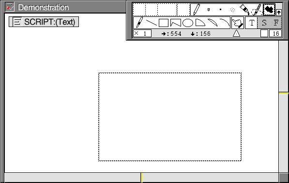
The white square on the far left of the top row is called the drawing palette, but it is also used with the painting tools for bitmap graphics. Put the finger-for-selecting over the white square and left click. A palette of patterns and colors will appear. The square to the right of the drawing palette is called the line palette, but it is also used to color text. By placing the finger-for-selecting above it and left clicking, a palette of colors will appear. To color text, first select the text with the finger-for-selecting, and then make a color selection through the line palette. To the right of the line palette are the line type palette (e.g., lines with arrows at the end of them) and the corner attributes palette, which works with the rectangle and polygon templates on the second row. Just select a corner rounding option, then select the rectangle or polygon template to see the effects. To the right of the corner attributes panel lie six tools for bit map graphics that are collectively called "art materials." They are activated by pressing the canvas tool just to the left of the small upward pointing arrow. After pressing the canvas tool, move the finger-for-selecting into the real object. A cross hairs pointer will appear. Use that to create a work area, as shown below in Fig. 2. This will also activate art materials tools, which will come to have a white background as in Fig. 2.
 |
|
|
The art materials tools from left to right are the pencil, eraser, paintbrush, airbrush, paint, and art cutter. You can select larger shapes for the eraser, paintbrush, and airbrush by left clicking the mouse with the finger-for-selecting on top of them. The paint tool acts like the paint bucket tool in other architectures, and the art cutter like the lasso. Different colors and patterns can be used with the paint tools by clicking on them and selecting a new color or pattern from the drawing palette. To change the background color of the real object itself, you have to go to the View menu and select the menu item for that purpose. The paint tool cannot be used for painting outside the work area created for it.
On the second line of the tool panel lies the templates for creating vector graphics. From left to right are the free curve, straight line, rectangle, polygon, ellipse, fan shape, bow shape, and elliptical arc. Just click them, and then start drawing shapes onto the MicroScript real object. They can also be used with different colors. Just click on them and select a new color from the drawing palette. Next to the vector graphics templates is the finger-for-selecting (cursor, pointer), and next to that are the text input tools: the stencil 'T', which is used to create a text field or character segment; the style 'S' and formatting 'F' tools. Just left click those to see the options available.
The third and final row of the tool panel contains the magnification display on the far left (left click to change the power up or down from 'x 1'), the pointer coordinates display, the triangulation point (used for changing the 0, 0 location of the window from the upper left hand corner of the window; left click on it and pull the tool into the window), and the grid display and grid spacing marks (left click on them to see the options). If you do not want to look at this panel, click the upward pointing arrow on the far right of the top row of the tool panel. This upward pointing arrow is officially called the sub panel display mark.
Needless to say, the best way to learn how to use the drawing and painting tools is to just click on them one by one and then experiment with them inside the MicroScript real object. Since the MicroScript comes equipped with only a small number of drawing and painting tools, it should take a person with previous computer art work experience only a few hours to master their operation. Once that has been achieved, you will then be able to rapidly create interface elements for your MicroScript programs, which will greatly speed up your software development projects on Cho Kanji and/or PMC T-Shell.
Now, let's move on to creating some basic MicroScript programs that incorporate graphical elements.
In previous chapters we have discussed how things were done using programming languages developed many decades ago. The biggest difference between those languages and a modern scripting language such as MicroScript lies in how graphics are put on the screen of a computer. Simply put, traditional languages such as BASIC and C language have statements and/or functions that allow a programmer to describe shapes, such as lines and circles, in his source code, while MicroScript does not. However, system calls that provide the same graphical functions as BASIC and C language can be called up from the underlying BTRON-specification operating system, although this is something that is intended for professional programmers, not the absolute beginners that this introductory course to MicroScript is aimed at.
Now, the absolute beginner might be wondering why this is the case, and the reason is quite easy to understand. When languages such as BASIC and C language were developed, there were no operating systems that provided easy-to-use graphics tools or programming routines at the operating system level. Accordingly, even if you wanted to do something simple, such as put vertical and horizontal lines around columns of numbers, you had to write a program to do it. To put it another way, the operating systems of many decades ago were closer to the tiny ITRON-specification real-time kernel on top of which BTRON middleware runs. They didn't have a mouse, graphics capabilities, a window system, or menus, which is why they were mainly used for word processing. Today's systems have all those capabilities, and thus it is easier to directly draw and paint the graphical elements we wish to incorporate in our programs, rather than describe them in computer program source code.
Having said that, it should be pointed out that we can simulate the processing of graphics via computer commands using MicroScript. Let's take the simplest example, drawing a line from left to right, which is one of the first things they teach you when you learn a traditional programming language, such as BASIC. In order to keep the size of our graphic images down to manageable size, let's pretend we are programming a personal digital assistant (PDA) with a screen size of 240 x 320 dots. In order to run the program, we have created a background named "Background" and made it yellow to match it to the background color of TRON Web's page (see Fig. 3 below). On top of that, we have drawn a horizontal line in the middle of the background using the straight line tool, which we named "Line," and to run the program, we have input the following script.
| MicroScript script "FigPro1" |
# Wipe Screen with Line in Place # # This script simulates a line being drawn by wiping the # screen from left to right to reveal a line segment put in # place beforehand using one of the drawing tools. VERSION 3 PROLOGUE WSIZE 240, 320 SCENE Background, Line :WIPE_R 500 END |
In MicroScript script "FigPro1," we introduce the handy window size statement, WSIZE, which perfectly matches the runtime window frame to the background. The alternative to this is to painstakingly match the work time window frame to the background, which may require a few rounds of trial and error to get a perfect match. One line below, we see our usual SCENE statement, but with something added to the right. It is the effect :WIPE_R, which means wipe the screen from left to right. The number "500" to the right indicates the speed of the window wipe. That number can be made lower or higher to speed up or slow down the window wiping effect.
In addition to wiping a window, MicroScript possesses a second way to simulate the drawing of a line on the screen, and that is to create a copy of a dot segment in neighboring pixel after neighboring pixel using the :DUP effect of the MOVE statement. That, of course, means we have to use the counter, which makes our program more complicated than a similar program in BASIC. On the other hand, the :DUP effect, which is actually intended as a tracking mechanism, can duplicate any segment, which gives you the ability to do something you cannot do using traditional versions of BASIC. To run this program, we simply create a dot on the screen named "Dot," and then enter the following script.
| MicroScript script "FigPro2" |
# Duplicate Dot to Create Line # # This script simulates a line being drawn by making copies # of a dot segment created beforehand using the drawing tools. VERSION 3 VARIABLE A:I PROLOGUE WSIZE 240, 320 SCENE Background APPEAR Dot MOVE Dot: 100, 0 @ CALL Line_Maker END FUNC Line_Maker SET A=100 REPEAT 100 SET A=$CNT+1 MOVE Dot: A, 100 @ :DUP SLEEP 50 ENDREPEAT END |
MicroScript script "FigPro2" should be pretty easy to understand to people who have mastered the contents of the previous chapters. In the first block of code we declare the variable 'A' that is an integer; in the second block of code, we size the window, put the background in place, display and move the segment "Dot" into place (the segment to be duplicated can be anywhere on the screen, but here it is directly underneath the line that will be drawn; the '@' means we are using the upper left hand corner of the screen as the 0, 0 location), and then we call up the function "Line_Maker"; and, finally, in the third block of code we are duplicating and moving the segment "Dot" 100 spaces to the right (the SLEEP statement is used so the we can see the line being drawn). Please keep in mind that there is a limit to how many times a segment can be copied (i.e., 16,380 copies), so use this function wisely.
Needless to say, using similar techniques as the two above, we could simulate the drawing of circles on the screen, but the easiest thing to do, which also saves time, is to create a circle using the drawing tools and then display it on the screen. The advantage to using drawing tools to create figure segments for our programs is that it allows us to create quite detailed graphic elements in a relatively short period of time, thus saving us from hours upon hours of tedious programming.
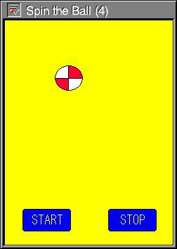
The first MicroScript program ever put on TRON Web was an animation program that moved a square around the screen from one location to the other. It is also possible to create animations by moving one figure over another in rapid succession, thus creating an animation in place. As an example of this we have created the program below, which displays a red and white ball (see Fig. 3) and the inverted image of it, thus creating the illusion of a spinning ball.
| MicroScript script "FigPro3" |
# Spin the Ball (1) # # This script simulates the spinning of a ball on the screen # by rapidly interchanging two ball figure segments in # succession. One ball is the inverse of the other ball. VERSION 3 VARIABLE A: I PROLOGUE WSIZE 240, 320 SCENE Background CALL Ball_Spin END FUNC Ball_Spin REPEAT 20 SET A=$CNT+1 APPEAR Ball1 SLEEP 150 DISAPPEAR Ball1 APPEAR Ball2 SLEEP 150 DISAPPEAR Ball2 ENDREPEAT END |
MicroScript script "FigPro3" is another script that should be easy to understand for readers who have mastered everything up to this point. In the first code block we declare an integer variable; in the second code block we size the window, put the background in place, and call up the function that will "spin" the ball; and in the third code block we make the two graphic elements "Ball1" and "Ball2" rapidly appear and disappear. The only things that should be pointed out are: (1) Ball1 and Ball2 have been put on top of each other and moved into place beforehand under the background at 72, 165 (hence there is no MOVE statement), and (2) that the SLEEP time may have to be adjusted depending on how fast or how slow the programmer's hardware is. In fact, if a MicroScript programmer has a very fast computer, this image on top of image animation technique could be used to "spin the globe" or show a short "motion picture" using a series of rapidly photographed JPEG images.
Now, let's expand MicroScript script "FigPro3" and make it so the spinning red and white ball goes up and down like a yo-yo. This will give us two animations at the same, and make the program--and our programming skills--more impressive.
| MicroScript script "FigPro4" |
# Spin the Ball (2) # # This script makes the simulated spinning ball in the # previous program move up and down in yo-yo fashion. The two # actions seem to take place simultaneously. VERSION 3 VARIABLE A: I VARIABLE B: I PROLOGUE WSIZE 240, 320 SCENE Background EXECUTE Ball_Spin, Ball_Yoyo END ACTION Ball_Spin REPEAT 20 SET A=$CNT+1 APPEAR Ball1 SLEEP 150 DISAPPEAR Ball1 APPEAR Ball2 SLEEP 150 DISAPPEAR Ball2 ENDREPEAT END ACTION Ball_Yoyo REPEAT 5 SET B=$CNT+1 MOVE Ball1: 72, 165 @ MOVE Ball2: 72, 165 @ SLEEP 1000 MOVE Ball1: 72, 65 @ MOVE Ball2: 72, 65 @ SLEEP 1000 ENDREPEAT END |
Since MicroScript script "FigPro4" is going to do two things at once, it should come as no surprise that two integer variables are declared in the first code block. It should also come as no surprise that since we need two procedures to do two things simultaneously, we have introduced the EXECUTE statement in the second code block, which executes the procedures "Ball_Spin" and "Ball_Yoyo." The two procedures are very similar--one makes Ball1 and Ball2 appear and disappear, while the other makes Ball1 and Ball2 go up and down 100 pixels. The only problem one might have with this script is matching the SLEEP intervals to the processor speed of the execution platform. Moreover, it should also be noted that error messages will be generated by putting a hyphen, '-', between 'Yo' and 'yo'. That is not permissible, because '-' is a mathematical operator.
One thing that is bad about MicroScript script "FigPro4" is that is executes for a fixed number of times, and then it turns off. Wouldn't it be nice if we could turn the program on and off at will? Well, we can do that if we add two new figure segments in the form of start and stop buttons, which can be seen in Fig. 3. This also requires us to write two new procedures to receive mouse inputs to start and stop the procedures that do the spinning and yo-yoing.
| MicroScript script "FigPro5" |
# Spin the Ball (3) # # This script introduces start and stop buttons to control # the spinning and yo-yoing of the ball that takes place in the # program. Note no values next to the REPEAT statements. VERSION 3 VARIABLE A: I VARIABLE B: I PROLOGUE WSIZE 240, 320 SCENE Background, But1, But2 EXECUTE Start, Stop # Not necessary; see explanation below END ACTION Ball_Spin REPEAT SET A=$CNT+1 APPEAR Ball1 SLEEP 150 DISAPPEAR Ball1 APPEAR Ball2 SLEEP 150 DISAPPEAR Ball2 ENDREPEAT END ACTION Ball_Yoyo REPEAT SET B=$CNT+1 MOVE Ball1: 72, 165 @ MOVE Ball2: 72, 165 @ SLEEP 1000 MOVE Ball1: 72, 65 @ MOVE Ball2: 72, 65 @ SLEEP 1000 ENDREPEAT END ACTION Start PRESS But1 EXECUTE Ball_Spin, Ball_Yoyo END ACTION Stop PRESS But2 TERMINATE Ball_Spin, Ball_Yoyo END |
At first glance, MicroScript script "FigPro5" is little more than a slightly expanded version of the previous script, MicroScript script "FigPro4." The only things different are that we added two procedures at the bottom to take mouse inputs from the buttons on the screen and start and stop Ball_Spin and Ball_Yoyo, and that we placed the names of those procedures next to the EXECUTE statement in the second code block. However, since an input from the end user will actually start and stop the program, which is to say the program is no longer self executing, the EXECUTE statement in the second code block is now unnecessary, although the program will run with it there. So the second code block now does nothing more than size the window and put the background and buttons in place.
Another thing that is a little tricky is the PRESS statement. Personal Media recommends that we use the FUNC statement with the CALL statement. So in the case of a single button, we would have FUNC preceding PRESS. However, this will generate an error message. The PRESS statement must always be preceded by the ACTION statement.
Finally, let's turn our program into a masterpiece by adding a little audio feedback to let the end user know that has clicked a button. This can be easily done by adding the BEEP statement to the two code blocks at the bottom of MicroScript script "FigPro5."
 |
|
|
| MicroScript script "FigPro6" |
# Spin the Ball (4) # # This script introduces audio feedback in the form of beeping # when either the Start or Stop button is clicked. Otherwise, # it does the same ball spinning and yo-yoing of the previous # script. VERSION 3 VARIABLE A: I VARIABLE B: I PROLOGUE WSIZE 240, 320 SCENE Background, But1, But2 END ACTION Ball_Spin REPEAT SET A=$CNT+1 APPEAR Ball1 SLEEP 150 DISAPPEAR Ball1 APPEAR Ball2 SLEEP 150 DISAPPEAR Ball2 ENDREPEAT END ACTION Ball_Yoyo REPEAT SET B=$CNT+1 MOVE Ball1: 72, 165 @ MOVE Ball2: 72, 165 @ SLEEP 1000 MOVE Ball1: 72, 65 @ MOVE Ball2: 72, 65 @ SLEEP 1000 ENDREPEAT END ACTION Start PRESS But1 BEEP 1000, 500 EXECUTE Ball_Spin, Ball_Yoyo END ACTION Stop PRESS But2 BEEP 1000, 500 TERMINATE Ball_Spin, Ball_Yoyo END |
MicroScript script "FigPro6" is little different from the preceding script, MicroScript script "FigPro5." It simply has "BEEP 1000, 500" added to the two bottom procedures. We include it here because it is "fully debugged." To understand what we mean, copy the second code block in MicroScript script "FigPro5" and replace the second code block in MicroScript script "FigPro6" with it. What will happen is that you will get unwanted audio feedback at the startup of the program, a result of the unnecessary EXECUTE statement in the second code block. When you erase the line in red with the unnecessary EXECUTE statement, the script will function as expected.
Although the four short programs above seem trivial to the untrained eye, we have in fact learned some powerful programming techniques. Specifically, we have learned how to create two types of animation and execute them simultaneously, we have learned how to create buttons and start and stop scripts from them, and we have learned how to send the end user audio feedback. Most importantly, by doing all of this with less than 40 lines of source code, we have demonstrated to the novice programmer the power of a well designed scripting language. With a well designed scripting language, even a beginner can write impressive programs if he is willing to put a little time and effort into learning the language.
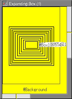
There are other kinds of animation we can create. We can, for example, create an animation that presents the illusion of an object that seems to be moving toward us. This illusion is based on showing a series of progressively larger versions of the same image. In Fig. 4 below, we give the simplest example, 10 progressively smaller hollow boxes, which is to say boxes with the same color as the background. By displaying these in rapid succession from the innermost to the outermost, we create the illusion of a black frame coming toward us.
 |
|
|
A script that can run this illusion is given below in MicroScript script "FigPro7." Anyone who has understood the contents of the chapters up to this point can easily understand this script. In fact, he will probably be struck by the simplicity and repetitiveness of the script. In the previous chapter, we introduced a similar lengthy, repetitive script for character streaming, and there wasn't anything we could do about it in terms of coding, because MicroScript doesn't allow us to put a variable between '%' and 's'. However, in this case there is a coding solution, and that is to introduce an "array variable."
| MicroScript script "FigPro7" |
# Expanding Box (1) # # This script displays a series of progressively larger boxes # giving the appearance of a box expanding and/or coming # closer and closer to the user. VERSION 3 VARIABLE A: I PROLOGUE WSIZE 240, 320 SCENE Background CALL Show_Boxes END FUNC Show_Boxes REPEAT 10 SET A=$CNT+1 APPEAR Box10 SLEEP 150 DISAPPEAR Box10 APPEAR Box9 SLEEP 150 DISAPPEAR Box9 APPEAR Box8 SLEEP 150 DISAPPEAR Box8 APPEAR Box7 SLEEP 150 DISAPPEAR Box7 APPEAR Box6 SLEEP 150 DISAPPEAR Box6 APPEAR Box5 SLEEP 150 DISAPPEAR Box5 APPEAR Box4 SLEEP 150 DISAPPEAR Box4 APPEAR Box3 SLEEP 150 DISAPPEAR Box3 APPEAR Box2 SLEEP 150 DISAPPEAR Box2 APPEAR Box1 SLEEP 150 DISAPPEAR Box1 ENDREPEAT END |
An array variable is nothing more than a single variable to which the programmer assigns multiple variables. These multiple variables can represent figure segments (graphical elements), numerical values, or characters, all of which will be demonstrated below. Moreover, based on what we have taught up to now, they can be used at both the global level by declaring them with the VARIABLE statement, or at the procedure level by declaring them with the LOCAL statement. A global variable can be used by all the procedures inside a MicroScript window, while a local variable can be used inside a particular procedure until it stops. Perhaps the most important point about array variables is that we use them to make our scripts smaller, easier to understand, and more efficient.
| MicroScript script "FigPro8" |
#                     Expanding Box (2)
#
# This script also displays the same series of progressively
# larger boxes to the same effect, but it does so with less
# code by using an array variable.

VERSION 3
SEGMENT B[10]

PROLOGUE
  SETSEG B[0] = Box10
  SETSEG B[1] = Box9
  SETSEG B[2] = Box8
  SETSEG B[3] = Box7
  SETSEG B[4] = Box6
  SETSEG B[5] = Box5
  SETSEG B[6] = Box4
  SETSEG B[7] = Box3
  SETSEG B[8] = Box2
  SETSEG B[9] = Box1
  CALL Show_Boxes
END

FUNC Show_Boxes
  REPEAT 10
    REPEAT 10
      APPEAR B[$CNT]
      SLEEP 150
      DISAPPEAR B[$CNT]
    ENDREPEAT
  ENDREPEAT
END
|
MicroScript script "FigPro8" does the same thing as MicroScript script "FigPro7." The main difference between the two is that the former does it with an array variable, and the latter does not, which is why it is a longer, repetitive script. MicroScript script "FigPro8" above is fairly easy to understand. We declare that there a series (array) of 10 figure segments with SEGMENT B[10], we set their values with the SETSEG statement between PROLOGUE and END, and then we make them appear and disappear with the procedure Show_Boxes, which has two REPEAT - ENDREPEAT loops, one for APPEAR and the other for DISAPPEAR.
The beginning programmer might like to point out that there is not such a big difference in the number of lines of code between MicroScript script "FigPro8" and MicroScript script "FigPro7," but that difference would grow dramatically if we had to expand the script to handle 100 boxes. Moreover, as the number of lines of code increases, the chances of processing slowing down also increases. Therefore, it is best to learn how to create array variables to write more compact code that is easy to manage and faster to execute.
| MicroScript script "ArrayPro1" |
# Numerical Array Variable (1) # # This script is an example of an array variable in which # numerical values, and not figure segments, are handled. It # is based on MicroScript script "FigPro8." VERSION 3 VARIABLE A: I[5] PROLOGUE SET A[0]=1 SET A[1]=2 SET A[2]=3 SET A[3]=4 SET A[4]=5 CALL Display_Numbers END FUNC Display_Numbers REPEAT 5 MESG "%d" A[$CNT] SLEEP 750 ENDREPEAT END |
MicroScript script "ArrayPro1" uses the same array variable structure as MicroScript script "FigPro8," but, in this case, it is applied to the integers 1 through 5. At the top of the script, we declare a numerical variable of five integer elements with the VARIABLE statement, we assign values to them with SET (as opposed to SETSEG above) between PROLOGUE and END, and then we display them in the system message panel using a REPEAT - ENDREPEAT loop.
Now, the intuitive beginner might look at this script and come to the conclusion that it could serve as the basis for creating a more compact script that would allow us to do all those arithmetic operations we did back in Chapter 3 inside a single script. Yes, that's quite true, and we give the basic structure of that in the program below.
| MicroScript script "ArrayPro2" |
# Numerical Array Variable (2) # # This script uses a numerical value array variable to do an # arithmetic operation. It is based on MicroScript script # "ArrayPro1." VERSION 3 VARIABLE A: I[5] PROLOGUE SET A[0]=1 SET A[1]=2 SET A[2]=3 SET A[3]=4 SET A[4]=5 CALL Display_Numbers END FUNC Display_Numbers LOCAL B: I SET B=2 REPEAT 5 MESG "%d" A[$CNT]*2 SLEEP 750 ENDREPEAT END |
MicroScript script "ArrayPro2" is almost the same as MicroScript script "ArrayPro1." The only difference is that there is a local variable in the procedure Display_Numbers, which we declared with the LOCAL statement and set the value of with the SET statement. Using cut and paste, this script can easily be expanded to do other arithmetic operations, such as addition. Just keep in mind that any new procedures have to have a different name from the existing procedure.
As for character array variables, there are two examples on p. 265 of Personal Media Corporation's An Introduction to BTRON MicroScript, which we give below.
| MicroScript script "ArrayPro3" |
# Character Array Variable (1) # # This script is an example of a character array variable. # It is a program example that appears on p. 265 of "An # Introduction to BTRON MicroScript." VERSION 3 VARIABLE CharString:C[10] PROLOGUE SET CharString[:]="ABCDEFG" MESG "Character String = %s" CharString END |
MicroScript script "ArrayPro3" displays the character string "ABCDEFG" in the system message panel. The only noteworthy thing about it is that there are less elements that have been set than declared. Note that the script works fine in spite of that.
| MicroScript script "ArrayPro4" |
# Character Array Variable (2) # # This script is an example of a character array variable. # It is a program example that appears on p. 265 of "An # Introduction to BTRON MicroScript." VERSION 3 VARIABLE CharString:C[10] PROLOGUE SET CharString[:]="ABCDEFG" MESG "Character String = %5.3s" CharString END |
MicroScript script "ArrayPro4" displays the character string "ABC" in the system message panel, and it offsets them five spaces to the right. What it demonstrates is that you do not have to use all the elements of an array variable.
In this chapter we introduced very important information that will allow us to create valuable programs in the future. Let's now review this so that it will stick in our minds.
|
|
|
|
|
|
|
|
|
|
|
MicroScript is capable of displaying many visual effects. In this chapter we introduced the :WIPE_R effect with the SCENE statement, which wipes the screen from left to right. |
|
|
The MOVE statement can be used with the :DUP effect, which creates copies of an image on the screen for each place it is moved to. The image that is copied can be anywhere on the screen. |
|
|
MicroScript can easily display images created inside the MicroScript window using the APPEAR and DISAPPEAR statements, or images inside a real object using the VOPEN and VCLOSE statements. In addition, it can create spatial animation using the MOVE statement, in-place animation using the APPEAR and DISAPPEAR statements to rapidly display one image over another, and depth animation using the APPEAR and DISAPPEAR statements to rapidly display a series of magnifications of the same image. |
|
|
An array variable is a single variable to which the programmer assigns multiple variables. These variables can represent figure segments (graphical elements), numerical values, or characters. |
|
|
In order to display figure segments using an array variable, we first declare the number of elements using the SEGMENT statement, and then assign values to the elements of the array using SETSEG statement. |
|
|
A variable can be set at the global level using the VARIABLE statement, and at the procedure level using the LOCAL statement. |
|
|
You can declare more elements for an array variable than you actually set, and you do not have to use all of the elements that you do set. |
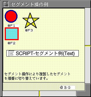
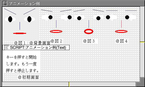
Personal Media Corporation bundles a large collection of MicroScript sample programs in its Cho Kanji operating system package for end users. Below are two of these that deal with graphical output. The first copies and displays in a predefined order three figure segments. The second is an animation example in which a funny face is displayed. The art work with translations is at the bottom of each script.
| Cho Kanji MicroScript sample script "Segment Operation Example" |
# Cho Kanji Sample Script # Segment Operation Example # # This script copies and then displays in a predefined order # the three figure segments that are shown in Fig. 5. # # Segment Control Example # VERSION 3 # SEGMENT X[4] # X0,X1,X2,X3 VARIABLE f:I # # PROLOGUE SCENE BG SETSEG X0=F1 SETSEG X1=X0 SETSEG X2=X0 SETSEG X3=X0 MOVE X0:10,10,@ MOVE X1:60,60,@ MOVE X2:110,110,@ MOVE X3:160,160,@ APPEAR X0,X1,X2,X3 SET f=1 EXECUTE do() END # ACTION do REPEAT SLEEP 1000 IF f==1 SETSEG X0=F1 SET f=2 ELSEIF f==2 SETSEG X0=F2 SET f=3 ELSE SETSEG X0=F3 SET f=1 ENDIF ENDREPEAT END |
 |
|
|
| Cho Kanji MicroScript sample script "Animation Example" |
#                 Cho Kanji Sample Script
#                Animation Example Script
#
# This script displays a funny face on the screen and then
# animates it. Execution begins by pressing the Tab key. By
# pressing the Escape key the script will stop.
#
# Animation Example Script
#
VERSION 3
#
DEFINE DisplayFrequency 50 # msec
DEFINE No_of_Scenes 4
VARIABLE Scene:I,Cut:S[No_of_Scenes]
#
PROLOGUE
 SCENE Initial_Screen
 SET Cut[:]=Fig4,Fig1,Fig2,Fig3
 SET Scene=-1
 # Matches the positions of Figs2-4 to the position of Fig1
 MOVE Fig2,Fig3,Fig4:Fig1.X,Fig1.Y,@
END
#
FUNC Animation()
 LOCAL t:I
 REPEAT
  # We use ; so that it is not suspended midway.
  SET t=$MSEC	# Present time
  DISAPPEAR Cut[Scene];
  SET Scene=(Scene+1)%No_of_Scenes;
  APPEAR Cut[Scene]
  # Elapsed time
  SET t=($MSEC-t)&0x7FFFFFFF
  IF t<DisplayFrequency
   SLEEP DisplayFrequency-t
  ENDIF
 ENDREPEAT
END
#
ACTION Start() KEY
 IF Animation.S!=0
  TERMINATE Animation # Stop
 ELSE
  IF Scene==-1
   SCENE Background_Screen # We display the background
                           # at the very beginning
  ENDIF
  EXECUTE Animation() # Start
 ENDIF
END
#
|
 |
|
|
|
TRON Web would once again like to thank Mr. Daishin Nakamura of Personal Media Corporation, who kindly offered his help in writing some of the scripts in this chapter. Without his help, this new introduction to BTRON MicroScript would not have been possible.
Copyright © 2012 Sakamura Laboratory, University Museum, University of Tokyo