
Besides being able to be put to practical use as is as a highly functional embedded control board that runs T-Kernel, Teaboard was developed by focusing also on T-Engine software training uses, such as T-Kernel, T-Kernel Extension, and T-Monitor in IT-related educational institutions. For that reason, it is different from the conventional T-Engine development kits and µT-Engine, and thus we have equipped it with many distinctive interfaces convenient for practice, such as a 7-segment LED, a buzzer, a temperature sensor, and various types of switches. Moreover, reflecting the network society of the present, we have provided it with a 10/100Base-TX network function as standard equipment.
In this article, we give an explanation centering on the distinctive hardware of Teaboard [Note 1].
Hardware Configuration
Teaboard/ARM920-MX1 consists of one CPU board.
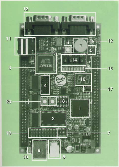
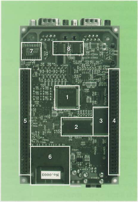
We show the configuration of the CPU board in Figs. 1 and 2.
 |
 |
|
|
|
|
|
We have loaded the following devices and peripheral interfaces onto the CPU board.
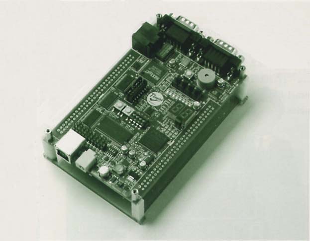
Moreover, the CPU board can also be utilized by mounting it on a development bench, in the same manner as other T-Engine and µT-Engine development kits. We show in Fig. 3 its appearance mounted on the development bench.
 |
|
|
Function Specification
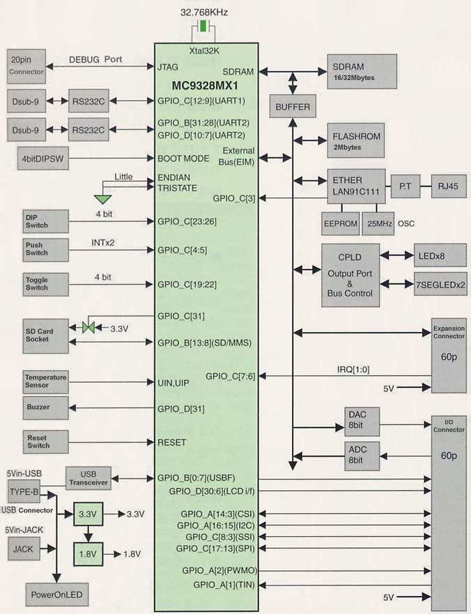
We show in Table 1 the detailed function specification. Also, in Fig. 4, we show the system configuration diagram.
|
|
|
| Item | Specification |
| CPU | MC9328MX1 (ARM920T core, 200 MHz) |
| Flash ROM | 2 megabytes (MB29LV160TE) |
| SDRAM | 16 megabytes (MT48LC4M16A2TG-75 [Mictron] x 2) |
| Ethernet | LAN91C111 100/10Base-T 1 ch |
| Serial | 2 ch (MC9328MX1 built-in UART) RS-232C |
| General-purpose switches | 8-bit (4-bit DIP SW, 4-bit toggle switch) |
| General-purpose LED | 8-bit |
| 7-segment LED | 2 figures |
| SD card socket | 1 slot (MC9328MX1 built-in controller) |
| Connector: 14-5638-009-511-862 (Kyocera Elco) | |
| Buzzer | Piezoelectric (MEB-12C5) |
| Temperature sensor | LM61 (National Semiconductor) |
| 8-Bit A/D converter | 1 ch EIM connection ADC08061 |
| 8-Bit D/A converter | 1 ch EIM connection AD7801 |
| USB function | 1 ch (Full speed, MC9328MX1 built-in controller) |
| I/O connector | Connector: PS-60PE-D4T1-B1E (JAE) unmounted |
| Expansion bus connector | Connector: PS-60PE-D4T1-B1E (JAE) unmounted |
| JTAG interface | Connector: 146134-9 (AMP) |
| CPLD write connector | Connector: 87832-1420 (Molex) |
 |
|
|
CPU
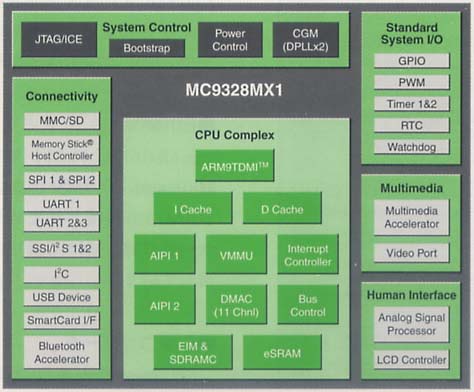
The CPU is the MC9328MX1 (DragonBall i.MX1) equipped with the ARMv5 core (ARM920T).
 |
|
We show in Table 2 the MC9328MX1 specification, and in Fig. 5 its function block diagram.
|
|
|
| CPU core | ARM920T (max. 200 MHz) |
| Process | 0.18 µm |
| Instruction cache | 16 kilobyte |
| Data cache | 16 kilobyte |
| Built-in SRAM | 128 kilobyte |
| DMA | 11 ch |
| UART | 2 ch |
| Timer | 2 ch |
| WatchDog | 1 ch |
| RTC | 1 ch |
| PWM | 1 ch |
| SSI/I2S | 1 ch |
| I2C | 1 ch |
| Camera I/F | Exists |
| USB | USB1.1 Device |
| MMC/SD controller | 1 ch |
| Memory Stick controller | 1 ch |
| PCMCIA controller | None |
| SIM card I/F | 1 |
| SPI | 2 ch |
| IrDA | v1.0 supportable with UART |
| A/D converter | Exists |
| LCD controller | RGB 16bit/STN, CSTN, TFT |
| Bluetooth | Support with Bluetooth accelerator |
| Multimedia accelerator | Exists |
| SDRAM support | Exists |
| NOR Flash support | Exists |
| Sym Flash support | Exists |
| M-system NAND Flash support | Exists |
| GPIO | 110 ch |
| Core voltage | 1.8 ~ 2.0 V |
| I/O voltage | 1.7 ~ 2.0V, 2.7 ~ 3.3V |
| Package | 14 x 14 mm, 256-pin, MAPBGA |
The MC9328MX1is the first product in the i.MX application processor family. An i.MX application processor is one in which peripheral modules have been integrated to a high degree around the ARM core. Employing outstanding power management technology, it is suited to developing multimedia devices with outstanding cost performance. In particular, the MC9328MX1 is equipped with a multimedia accelerator (MMA), and thus high performance and low power consumption coexist with each other.
Furthermore, as for the CPU hardware performance, operation at a maximum of 200 MHz is possible, but in the case of Teaboard, from the influence of providing a common clock to the USB function, the CPU will run at a clock speed of 192 MHz. At this time, the memory bus operation clock becomes 96 MHz.
SDRAM
As for the main memory, we have implemented two 64-megabit SDRAMs. The SDRAMs are controlled by a controller built into the MC9328MX1. Memory capacity is 16 megabytes, which is connected via a 32-bit wide bus. The CAS latency becomes two clocks when the bus is at 100 MHz.
Flash ROM
We have implemented one Flash memory of 16 megabits. Memory capacity is 2 megabytes, which is connected via a 16-bit wide bus. The access time is 90 nanoseconds.
Ethernet
The Ethernet controller is 10/100Base-TX compatible, and it is connected to the local bus (EIM). We are using the LAN91C111 (SMSC) for the controller.
D/A Converter
An 8-bit parallel D/A converter is connected to the local bus (EIM). The analog output of the D/A converter is connected to the I/O connector.
A/D Converter
An 8-bit parallel A/D converter is connected to the local bus (EIM). The analog input of the A/D converter is connected to the I/O connector.
LEDs
Two 7-segment LEDs and an 8-part chip LED are together connected to the local bus (EIM).
Temperature Sensor
A temperature sensor is connected to the U channel of the Analog Signal Processor (ASP) module built into the MC9328MX1. A National Semiconductor LM61 is sued for the temperature sensor.
General-Purpose Switches
A push switch, a toggle switch, and a DIP switch are connected together to the GPIO (General Purpose Input/Output) port of the MX9328MX1. In a case where the GPIO has been set to input, because it can also be made an interrupt source, the push switch can also be used as is as a switch for interrupt test use.
Expansion Bus Connector
For external expansion use, the MC9328MX1 local bus (EIM) is signal connected. We show in Table 3 the pin arrangement of the expansion bus connector.
|
|
|||||
|
|
|
|
|
|
|
|
|
GND |
|
|
GND |
|
|
|
D14 |
|
|
D15 |
|
|
|
D12 |
|
|
D13 |
|
|
|
D10 |
|
|
D11 |
|
|
|
D8 |
|
|
D9 |
|
|
|
GND |
|
|
D7 |
|
|
|
D6 |
|
|
D5 |
|
|
|
D4 |
|
|
D3 |
|
|
|
D2 |
|
|
D1 |
|
|
|
D0 |
|
|
GND |
|
|
|
EB3 |
|
|
EB2 |
|
|
|
OEB |
|
|
RWB |
|
|
|
GND |
|
|
CS4B |
|
|
|
CS3B |
|
|
EXT_INT1 |
|
|
|
EXT_INT0 |
|
|
GND |
|
|
|
CLK0 |
|
|
GND |
|
|
|
A23 |
|
|
A22 |
|
|
|
A21 |
|
|
A20 |
|
|
|
A19 |
|
|
A18 |
|
|
|
A17 |
|
|
A16 |
|
|
|
GND |
|
|
A15 |
|
|
|
A14 |
|
|
A13 |
|
|
|
A12 |
|
|
A11 |
|
|
|
A10 |
|
|
A9 |
|
|
|
A8 |
|
|
GND |
|
|
|
A7 |
|
|
A6 |
|
|
|
A5 |
|
|
A4 |
|
|
|
A3 |
|
|
A2 |
|
|
|
A1 |
|
|
A0 |
|
|
|
VIN |
|
|
VIN |
|
We use the general-purpose PS-60PE-D4T1-B1E (JAE) for the expansion bus connector (connector not implemented).
I/O Connector
By using an I/O connector, we can utilize the following among the various types of control functions built into the CPU.
These signals can also be utilized as GPIO signals. Moreover, A/D converter input and D/A converter output are also connected to the I/O connector.
We show in Table 4 the pin arrangement of the I/O connector.
|
|
|||||
|
|
|
|
|
|
|
|
|
AGND |
|
|
ANALOG OUT |
|
|
|
ANALOG IN |
|
|
GND |
|
|
|
PC17/SPI1_MOSI |
|
|
PC16/SPI1_MISO |
|
|
|
PC14/SPI1_SCLK |
|
|
PC15/SPI1_SS |
|
|
|
PB14/SIM_SVEN/SSI_RFXS |
|
|
PB15/SIM_PD/SSI_RXCLK |
|
|
|
PB16/SIM_TX/SSI_RXDAT |
|
|
PB17/SIM_RX/SSI_TXDAT |
|
|
|
PB18/SIM_RST/SSI_TXFS |
|
|
PB19/SIM_CLK/SSI_TXCLK |
|
|
|
GND |
|
|
PA16/12C_SCL |
|
|
|
PA15/12C_SDA |
|
|
PA14/CSI_PIXCLK |
|
|
|
PA13/CSI_HSYNC |
|
|
PA12/CSI_VSYNC |
|
|
|
PA11/CSI_D7 |
|
|
PA10/CSI_D6 |
|
|
|
PA9/CSI_D5 |
|
|
PA8/CSI_D4 |
|
|
|
PA7/CSI_D3 |
|
|
PA6/CSI_D2 |
|
|
|
PA5/CSI_D1 |
|
|
PA4/CSI_D0 |
|
|
|
PA3/CSI_MCLK |
|
|
PA1/TIN |
|
|
|
PA2/PWM0 |
|
|
GND |
|
|
|
PD30/LD15 |
|
|
PD29/LD14 |
|
|
|
PD28/LD13 |
|
|
PD27/LD12 |
|
|
|
PD26/LD11 |
|
|
PD25/LD10 |
|
|
|
PD24/LD9 |
|
|
PD23/LD8 |
|
|
|
PD22/LD7 |
|
|
PD21/LD6 |
|
|
|
PD20/LD5 |
|
|
PD19/LD4 |
|
|
|
PD18/LD3 |
|
|
PD17/LD2 |
|
|
|
PD16/LD1 |
|
|
PD15/LD0 |
|
|
|
GND |
|
|
PD14/VSYNC |
|
|
|
PD13/HSYNC |
|
|
PD12/ACD_0E |
|
|
|
PD11/CONTRAST |
|
|
PD10/SPI_SPR/SPI2_TXD |
|
|
|
PD9/PS/SPI2_RXD |
|
|
PD8/CLS/SPI2_SSB |
|
|
|
PD7/REV/SPI2_CLK |
|
|
PD6/LSCLK |
|
|
|
GND |
|
|
VIN |
|
We use the general-purpose PS-60PE-D4T1-B1E (JAE) for the I/O connector (connector not implemented), which is the same as for the expansion bus connector .
SD Card
An SD card socket has been implemented on the rear side of the circuit board. The SD card controller signal of the MC9328MX1 is connected to the connector. A portion of the signals are connected to the GPIO.
Serial RS-232C
A 2-channel RS-232C interface (9-pin/male) has been implemented on the CPU side of the circuit board. The UART built into the MC9328MX1 is connected via the level converter to the RS-232C interface.
Buzzer
A piezoelectric buzzer has been implemented on the CPU side of the circuit board. The MEB-12C5 (small size/oscillating circuits built in) is used for the piezoelectric buzzer. The piezoelectric buzzer is connected via a driver to the GPIO of the MC9328MX1.
USB Function
On the CPU side of the circuit board, a USB TYPE-B terminal is implemented, and thus it is possible to use Teaboard as a USB 1.1 Full Speed (12 Mbps) USB device. The USB function controller of the MC9328MX1 is connected to the USB TYPE-B terminal.
Moreover, it is also possible to provide the board's 5V power supply from the USB TYPE-B terminal.
Power Supply Provision
Teaboard operates on a single power source of 5V ± 5%. Consumption of the 5V power supply current is 350mA/1.75W ~ 400mA/2W (state with the buzzer ON, LEDs completely lit), and power supply provision from the USB cable is kept to the so-called USB bus power permitted value (500 mA). It is possible to utilize either a USB TYPE-B connector or a DC jack to provide the power supply.
The 5V power supply that is provided is output to the buzzer, A/D converter, expansion connector, and I/O connector. Moreover, from the 5V power supply, the SW regulator generates 3.3V, which is supplied to the MC9328MX1, SDRAM, Flash ROM, CPLD, Ethernet controller, logic IC, temperature sensor, RS-232C level converter, and the D/A converter. By means of the 3-terminal regulator 1.8V for use by the CPLD and MC9328MX1 are generated from the 3.3V.
 |
|
|
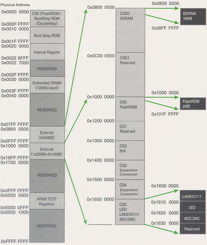
We show in Fig. 6 the organization of the memory map.
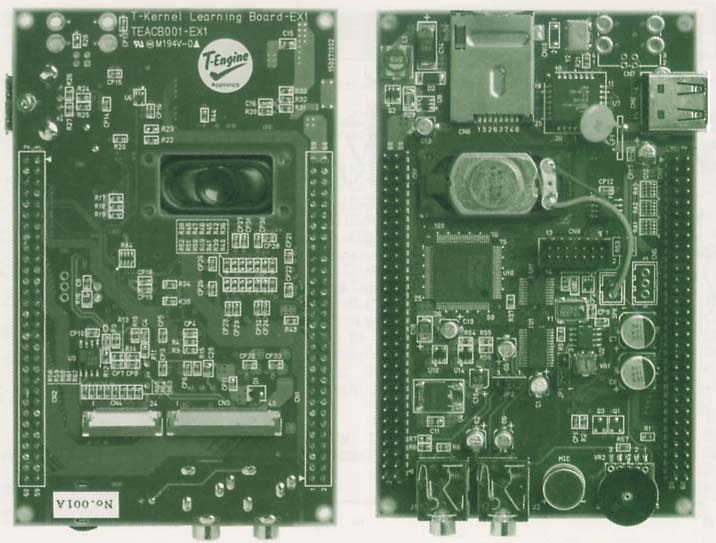
We are planning to put on sale an expansion board as an option product for Teaboard/ARM920-MX1. We show in Fig. 7 the appearance of the expansion board.
 |
|
|
The expansion board is connected to Teaboard through the expansion bus connector and the I/O connector, and thus it is possible to add to Teaboard an LCD interface, a touch panel interface, microphone input, speaker output, USB host, and eTRON chip interface functions. Moreover, through the LCD interface on the expansion board and touch panel interface, you can mount a touch panel LCD board and the same LCD board that is utilized on Standard T-Engine.
Teaboard/ARM920-MX1 is a highly functional embedded control board computer that is equipped with a number of distinctive I/O interfaces and a 10/100Base-T network function, and which, moreover, can as is put to practical use the results of the T-Engine project, such as T-Kernel and T-Kernel Extension. Furthermore, we would also like it utilized as an easy-to-purchase education and practice board matched to the education of modern embedded engineers. By using Teaboard, we would by all means like you to get a real feeling for the world of T-Kernel, which is a next generation standard real-time OS for embedded devices.
____________________
[Note 1] In this article we are explaining the latest information on Teaboard, which at the time the article was written is a product in development. Because there may also be cases where a portion of the specifications and so on are modified in the product that is finally put on sale, please be understanding beforehand. Please confirm the latest information at the time you purchase Teaboard.
The above article on Teaboard appeared on pages 29-35 in Vol. 95 of TRONWARE. It was translated and loaded onto this Web page with the permission of Personal Media Corporation.
Copyright © 2005 Personal Media Corporation
Copyright © 2008 Sakamura Laboratory, University Museum, University of Tokyo