
Teaboard is equipped with unique interfaces, such the push switch and the 7-segment LED. Because these interfaces are easy to deal with and their operations are easy to understand, they are most suitable in practicing program development.
In this article, we will introduce an example of program development in which the unique hardware of Teaboard is used [Note 1].
Outline of the Program
This is a simple roulette program. To instruct roulette start/stop, and to instruct terminating the program, we respectively use one each of the push switches on the Teaboard main unit. Moreover, in order to display the roulette rotation, we use the 7-segment LED on the Teaboard main unit.
We show the external specification of the program.
Also, we will make it our business to create the program on a T-Kernel base.
Flow of the Program
We show in List 1 the actual program list (main.c).
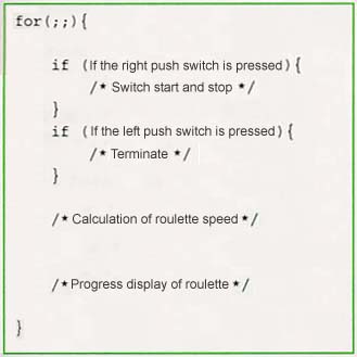
The flow of the program becomes as in Fig. 1. The main operations are carried out inside this for loop.
 |
|
|
First, by means of pressing down on the right push switch, start or stop are set in the variable start.
If it's start, the variable step is between from MAX=50000 to MIN=20000, and it changes 10 at a time. If it's stop, step gradually becomes smaller, and then finally it becomes 0.
As to the value of step, each time the program executes one round of the for loop, it is totaled in count. When count reaches 1000000, the LED moves forward by one, and count is reset to 0.
The main Function
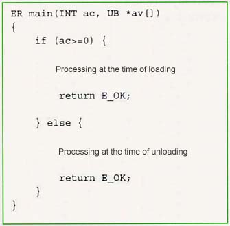
In the case of a T-Kernel program, the structure of the main function is basically made up in the manner of Fig. 2.
 |
|
|
In "processing at the time of loading," we carry out the necessary startup processing, such as task creation; startup; object creation of semaphores, etc.; and the registering of handlers. In av[1] ~ av[ac-1], an argument string is entered in ASCII/EUC code. In a case where processing has taken place normally, the program returns E_OK. In a case where it has failed, the program returns an error code (negative value) and terminates.
When loading succeeds, the program remains in memory (shared memory). If there is a case where is not necessary to leave the program in memory, we return a negative value on purpose.
In the roulette program on this occasion, because we are not particularly thinking about such things as real-time performance, we carry out all the roulette processing with the "processing at the time of loading" part of List 2. When we terminate the program by pressing the left switch, we return a negative value (-1) on purpose, and thus we make it so that the program will not remain in memory.
Display Operations of the LED
The put_led function carries out the actual operations of the 7-segment LED.
 |
|
|
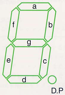
According to the "Teaboard Hardware Specification" attached to Teaboard, there is the description "the 7-segment LED is connected to the 0x16100000 and 0x16100002 addresses of the local bus (EIM) CS5 space addresses." With the value of the respective address (at the time of 16-bit access, the lower 8 bits), we control the lighting up (=0) / extinguishing (=1) of a segment. We show the location of the segments in Fig. 3. Also, in Table 1, we show the segment-to-bit correspondences.
|
|
|||||||||
|
|
|
|
|
|
|
|
|
|
|
| Right 7-Segment LED |
|
|
|
|
|
|
|
|
|
| Left 7-Segment LED |
|
|
|
|
|
|
|
|
|
In reading in the data, we use out_h. What we call out_h is a library function provided in the "I/O port access support function" of T-Kernel/SM (System Manager), which outputs data to the I/O port in half-word (16-bit) units. In the case of Teaboard, all I/O becomes memory map I/O; we do not access direct memory, rather, by using a specialized access function standardized in T-Kernel/SM, software portability and readability are raised.
Detection of the Push Button State
Detection of the push button state is carried out with the beginning of a for loop.
According to "Teaboard Hardware Specification," there is the description "the push switch is connected to GPIO Port C pins 4 and 5, and when the switched is depressed, "L" is input into the Port." For the details of the MC9328MX1 GPIO [Note 2], there is a description in the MC9328MX1 "Reference Manual." According to this, the GPIO Port C register is made up in the manner of Table 2. In regard to these, we make settings that use pins 4 and 5 for the GPIO, make the signal direction input , and mask the interrupt. In making the settings, we utilize out_w provided in the I/O Port access support function of T-Kernel/SM, which is also utilized in LED access. This outputs data to the I/O port in word (32-bit) units.
|
|
|
| Port C Data Direction Register (DDIR_C) |
|
| Port C GPIO in Use Register (GIUS_C) |
|
| Port C Sample Status Register (SSR_C) |
|
| Port C Interrupt Mask Register (IMR_C) |
|
In actuality, we can detect whether or not the switch is depressed by reading in SSR_C (Port C Sample Status Register). In the readout of SSR_C, we utilize in_w provided in the I/O port access support function of T-Kernel/SM. This reads out data from the I/O port in word (32-bit) units.
When the push switch is actually depressed, "L" is input to the port; the concerned bit of SSR_C at this time at this time becomes 0. Later, when the concerned bit of the readout value makes the 1 → 0 change, the button is regarded as depressed, and it comes about that the program moves into the respect processing.
 |
|
Compiling of the Program
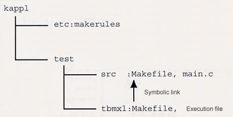
The actual program (main.c; List 1) is arranged in directory structure in the manner of Fig. 4. Generally, in program arrangement in the standard development environment, there are the following rules.
$ In -s ../src/Makefile Makefile
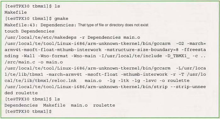
For the actual compiling, we only execute the gmake command in the directory used for actual file creation.
(1) Move to the kappl/roulette/tbmx1 directory (2) Execute the gmake command
If compiling and linking executes and there are no particular errors, the system returns to the command prompt.
We show in Fig. 5 the appearance of compiling.
 |
|
|
Executing Program Loading
Before we load the program, we create a startup disk for the propose of storing the execution file. After that, we actually load the execution program we compiled, and then we verify its operation.
To begin with, we create a startup disk.
(1)
- Connect the console to Teaboard, turn on the Teaboard power supply, and start up T-Kernel. On the console, the CLI prompt
- [/SYS] %
- will appear.
- In a case where the prompt
- TM>
- has appeared, because T-Monitor has started up, please input the bd command in the manner of
- TM> bd
- and start up T-Kernel.
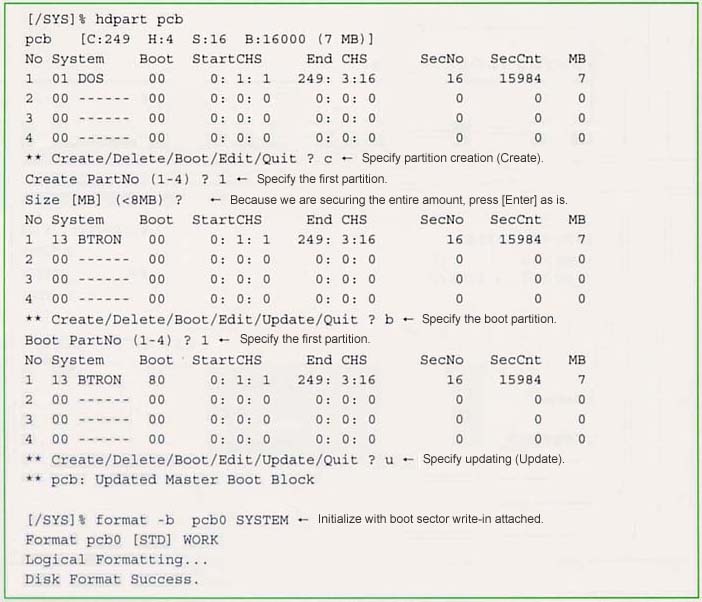
(2) Prepare one SD card for startup disk use, and then insert it in the SD card slot. (3) Set the partition by means of the hdpart command, and then format with the format command. We show in Fig. 6 the series of procedures. (4)
- Connect the work disk with the CLI's att command. Here we connect the SD card's first partition (logical device name pcb0) with the connection name of foo.
- [/SYS] % att pcb0 foo
(5)
- Once you are connected, copy the system file suite from the ROM disk with the rcp command.
- [/SYS] % rcp -b -r /SYS/foo/=
(6)
- Finally, restart Teaboard and confirm whether it can start up from the SD card. After restarting, execute the df command, and if the DEV item is made up as pcb0, it will come about that Teaboard will start up from the SD card. If it is made up as rda, it will come about that Teaboard will start up from the ROM disk.
- [/SYS] % df
- PATH DEV TOTAL . . .
- /SYS pcb0 32816 . . .
- Confirm whether the red part is made up as pcb0.
 |
|
|
By means of the work up to here, we have created a startup disk, and preparations have been made up to start up from the startup disk.
Continuing on, we will load the program and carry out the work of executing.
(1)
- With the CLI's recv command, we transmit the execution file onto Teaboard's startup disk.First, we start the recv command in the following manner on top of the console.
- [/SYS] recv -d -c roulette
(2) On Tera Term, select [File] - [Transfer] - [Xmodem], select the roulette execution file in the file selection dialog box, and then click [OK]. The file transfer dialog box will appear, and the file transfer will be carried out by Xmodem. When the transfer terminates, the dialog box will disappear. (3)
- Confirm on top of the CLI the operation of roulette. T-Kernel base programs execute by means of loading onto shared space with the lodspg command.
- [/SYS] % lodspg roulette
(4)
- To terminate the program, push the left push switch of Teaboard. At this time, the program will return a negative value and terminate, and it will not reside in the memory. For that reason, at the time of termination, the message
- roulette: Can't Loaded System Program -1
- will appear on top of the console. This is proper operation, and there is no problem.
Device Driver Outline
In the roulette example in the previous section, we directly controlled the LED from the program. However, one could say that it would be more desirable to, in general terms, separate the part that accesses hardware in this manner as an independent module and realize it as a device driver.
Device drivers are already familiar in the PC world. However, in the embedded world, particularly prior to the appearance of T-Engine, unified device driver interface specifications did not exist. Accordingly, in the T-Engine Forum, we have standardized a device driver interface specification as part of the T-Kernel specification, which additionally has standardized functions for the physical layer also, such as memory and I/O access. As a result, in both the case of the embedded application developer calling up a driver and the case of a driver developer developing a driver, it has come about that they can freely utilize device drivers and distributed them, if they just follow this device driver interface specification.
Determination of the Driver Specifications
We show in Table 3 the specifications of the LED driver we will create.
|
|
|||||||||||||||||||||||||||||||||||||||||||||||||||||||||||
|
"led" | ||||||||||||||||||||||||||||||||||||||||||||||||||||||||||
|
None | ||||||||||||||||||||||||||||||||||||||||||||||||||||||||||
|
|
||||||||||||||||||||||||||||||||||||||||||||||||||||||||||
In the design of drivers, the determination of four specifications is required beforehand in the following manner.
- Determination of the physical device name
- Determination of the block size of the specific data
- Determination of the attribute data specification
- Determination of the device event notification specification
Implementation of the Driver
Once the driver specifications have been decided, we at last implement the driver. We show in List 3 the actual program list (led.c).For the physical layer programming for the LED hardware, we carry out the reading/writing of data using the standardized I/O port access support functions in T-Kernel/SM.
For the programming of the logical layer, we use the simple device driver interface layer (SDI), which Teaboard provides independently as a library. This is an interface layer for simple devices that can terminate immediately, without changing to a device read/write wait state. Conversely, in regard to general devices that take time to read/write, we use the general-purpose device driver interface layer (GDI). By using this type of interface layer, we can do programming easier than directly using the T-Kernel/SM device registration function (tk_def_dev()).
In the simple device driver interface layer (SDI), we prepare the following six functions.
- main function
- open_fn function
- close_fn function
- read_fn function
- write_fn function
- event_fn function
Loading and Execution of the Driver
The device driver is also a type of T-Kernel base program. For that reason, it loads in shared space with the lodspg command in the same manner as the initial T-Kernel base roulette program. Once it loads, it resides in memory, and it can be freely called up and used from the application side.
In actually using it, we first execute in the manner of
tk_opn_dev("led", TD_UPDATE)
and open the device.
Afterward, if, for example, we read in data with something like tk_swri_dev() for the data number DN_LEDEC (= -203), the read-in value is displayed in the 7-segment LED with a decimal number.
|
|
||
| Device Name | "buzzer" | |
| Specific Data | None | |
| Attribute Data | Data Number | Data Structure |
| DN_BZmode = -200 | 0: OFF, 1: ON | |
In the same manner as the LED driver, we have also created a driver for the purpose of controlling the buzzer on Teaboard. We show in Table 4 the specification of the buzzer control driver that we have created. We show in List 4 the actual program list (buzzer.c).
Because the buzzer is connected to pin 31 of GPIO Port D, we turn ON/OFF the output to the buzzer by controlling the GPIO register inside the driver.
Finally, let's try making a simple timer using the LED control driver and the buzzer control driver.
While counting down for each number of seconds specified in the argument, we display the number of seconds in the 7-segment LED, and once we have reached zero, we ring the buzzer three times. We show in Fig. 7 the execution example. We show in List 5 the actual program list (timer.c).
 |
|
|
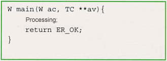
Here, we have created it as a process base program. In the case of a process base program, the main function structure basically becomes like that in Fig. 8. In av[1], av[2], . . . , av[ac-1], the command line argument character string is entered with a TRON Code character string. When we return from the main function, the process terminates, and it is cleared from the memory.
 |
|
|
In a case where we start up a process base program on the CLI, we directly input the file name. In the example on this occasion, the program starts up by inputting timer.
Above, we have taken a hurried look at an example of program development, from a simple T-Kernel base program to device drivers and a process base program.
Don't you get the feeling that programming with T-Kernel, which is well standardized, and Teaboard, which was designed to be easy to understand in learning use, is unexpectedly simple and easy to learn?
These types of sample programs for learning that serve as an aid in learning embedded programming are attached to Teaboard. Also, manuals and specifications are fully provided, and it is devised so that embedded programming practice can commence from the day that it is purchased.
Furthermore, the program lists introduced in this article are recorded on the CD-ROM attached to this issue. Please make reference together with this article.
____________________
| List 1 main.c (roulette program) |
/*
  Roulette
  Copyright (C) 2005 by Personal Media Corporation
 */

#include <tk/syslib.h>

/* Roulette position x (0 ~ 7) 7-segment LED display */
static void put_led( int x )
{
  /* +-a-+
     f   b  Correspondences of each segment and register bit
     +-g-+    bit7 = b, c, dot, d, e, g, f, a = bit0
     e   c
     +-d-+ dot */
  enum {b = 128, c = 64, dot = 32, d = 16, e = 8, g = 4, f = 2, a = 1};
  const unsigned char p[8][2] = { /* Pattern definition */
    {0, a}, {0, b}, {0, c}, {0, d}, {d, 0}, {e, 0}, {f, 0}, {a, 0}
  };

  out_h( 0x16100002, p[x][0] ^ 0xff ); /* Left 7-segment LED: Because 0 is lighting up and 1
                                          is extinguishing, we invert and write in */
  out_h( 0x16100000, p[x][1] ^ 0xff ); /* Right 7-segment LED:Because 0 is lighting up and 1
                                          is extinguishing, we invert and write in */
}

/* Main */
ER main( INT ac, UB *av[] )
{
#define GIUS_C 0x0021c220 /* GPIO Port C GPIO in Use Register */
#define DDIR_C 0x0021c200 /* GPIO Port C Data Direction Register */
#define SSR_C 0x0021c224 /* GPIO Port C Sample Status Register */
#define IMR_C 0x0021c230 /* GPIO Port C Interrupt Mask Register */
#define LEFT  (1 << 4) /* Left push switch bit location */
#define RIGHT (1 << 5) /* Right push switch push location */

  int position, count, step, start, prev, current;

  out_w( GIUS_C, in_w( GIUS_C ) | (LEFT | RIGHT) ); /* Use pin as GPIO */
  out_w( DDIR_C, in_w( DDIR_C ) & ~(LEFT | RIGHT) ); /* Make signal direction input */
  out_w( IMR_C, in_w( IMR_C ) & ~(LEFT | RIGHT) ); /* Mask interrupt */

  position = 0; count = 0; step = 0; start = 1; current = ~0;

  for(;;) {
    /* Push switch detection */
    prev = current;
    current = in_w( SSR_C );
    if ((current & RIGHT) == 0 && (prev & RIGHT) != 0) { /* If right switch is pressed */
      start = !start; /* Switching of start and stop */
    }
    if ((current & LEFT) == 0 && (prev & LEFT) != 0) { /* If left switch is pressed */
      break; /* End */
    }

    /* Fixing of the breadth of progression */
    if (start) { /* During revolution */
      const int MIN = 20000, MAX = 50000, D = 10;
      if (step < MIN) step = MIN + 1;
      else if (step & 1) { /* Speeding up */
	step = step + D;
	if (step > MAX) step = MAX;
      } else { /* Slowing down */
	step = step - D;
	if (step <= MIN) step = MIN + 1;
      }
    } else { /* While stopped */
      step = step * 699 / 700;
    }

    /* Proceed with roulette */
    count += step;
    if (count > 1000000) {
      count = 0;
      position++; if (position > 7) position = 0;
    }
    put_led( position ); /* LED display */
    WaitUsec( 1000 ); /* Wait for 1 millisecond */
  }

  return -1; /* Terminate */
}
|
| List 2 Makefile for the roulette program |
# # Roulette # Copyright (C) 2005 by Personal Media Corporation # # Source dependencies-related file (automatically generated) DEPS = Dependencies DEPENDENCIES_OUTPUT := $(DEPS) # T-Kernel base standard rules include ../../etc/makerules # Creation target TARGET = roulette # Path to where source file exist VPATH = ../src SRC = main.c OBJ = $(addsuffix .o, $(basename $(SRC))) CFLAGS += $(CFLAGS_WARNING) # ---------------------------------------------------------------------------- .PHONY: all clean all: $(TARGET) $(TARGET): $(OBJ) $(LINK.o) $(LDOBJS) $^ $(LOADLIBES) $(LDLIBS) $(OUTPUT_OPTION) $(STRIP) $@ clean: $(RM) $(OBJ) $(TARGET) $(DEPS) # Source dependencies-related ifdef DEPENDENCIES_OUTPUT $(DEPS): ; touch $(DEPS) else $(DEPS): $(SRC) ; $(MAKEDEPS) $@ $? endif include $(DEPS) |
| List 3 led.c (LED control driver) |
/*
  LED Control Device Driver
  Copyright (C) 2005 by Personal Media Corporation
 */

#include <tk/tkernel.h>
#include <device/sdrvif.h>

/* Data number definitions */
enum{
  DN_LE8BIT  = -200,  /* 8-bit LED attribute data number */
  DN_LE7SEGR = -201,  /* Right 7-segment LED attribute data number */
  DN_LE7SEGL = -202,  /* Left 7-segment LED attribute data number */
  DN_LEDEC   = -203   /* 7-segment LED 2-figure attribute data number */
};

static int dat8BIT, dat7SEGR, dat7SEGL, datDEC; /* Saving of attribute data */

/* Display of 8-bit LED */
static void set8BIT( int x )
{
  out_h( 0x16100004, x ^ 0xff ); /* As 0 is ON, 1 is OFF, write in using bit inversion */
  dat8BIT = x; /* Save attribute data */
}

/* Display of right 7-segment LED */
static void set7SEGR( int x )
{
  out_h( 0x16100000, x ^ 0xff ); /* As 0 is ON, 1 is OFF, write in using bit inversion */
  dat7SEGR = x; /* Save attribute data */
}

/* Display of left 7-segment LED */
static void set7SEGL( int x )
{
  out_h( 0x16100002, x ^ 0xff ); /* As 0 is ON, 1 is OFF, write in using bit inversion */
  dat7SEGL = x; /* Save attribute data */
}

/* 7-segment LED 2-figure display */
static void setDEC( int x )
{
  /* +-a-+
     f   b  Correspondences of each segment and register bit
     +-g-+    bit7 = b, c, dot, d, e, g, f, a = bit0
     e   c
     +-d-+ dot */
  enum {b = 128, c = 64, dot = 32, d = 16, e = 8, g = 4, f = 2, a = 1};
  const unsigned char p[] = {
    a|b|c|d|e|f  , /* Pattern of 0 */
      b|c        , /* Pattern of 1 */
    a|b  |d|e  |g, /* Pattern of 2 */
    a|b|c|d    |g, /* Pattern of 3 */
      b|c|    f|g, /* Pattern of 4 */
    a  |c|d  |f|g, /* Pattern of 5 */
    a  |c|d|e|f|g, /* Pattern of 6 */
    a|b|c        , /* Pattern of 7 */
    a|b|c|d|e|f|g, /* Pattern of 8 */
    a|b|c|d  |f|g  /* Pattern of 9 */
  };

  set7SEGR( (x >= 0) ? p[x % 10] : (x >= -9) ? p[-x] : 0 ); /* Position of 1 */
  set7SEGL( (x >= 10) ? p[(x / 10) % 10] : (x >= 0) ? 0 : (x >= -9) ? g : 0 ); /* Position of 10 */
  datDEC = x; /* Save attribute data */
}

/*
 * Read function: read-in processing
 */
static INT read_fn( ID devid, INT start, INT size, VP buf, SDI sdi )
{
  switch (start) {
  case DN_LE8BIT:
    if (size >= 1) { *(UB*)buf = dat8BIT; return 1; }
  case DN_LE7SEGR:
    if (size >= 1) { *(UB*)buf = dat7SEGR; return 1; }
  case DN_LE7SEGL:
    if (size >= 1) { *(UB*)buf = dat7SEGL; return 1; }
  case DN_LEDEC:
    if (size >= 1) { *(B*)buf = datDEC; return 1; }
  }
  return E_PAR;
}

/*
 * Write function: write-in processing
 */
static INT write_fn( ID devid, INT start, INT size, VP buf, SDI sdi )
{
  switch (start) {
  case DN_LE8BIT:
    if (size >= 1) { set8BIT( *(UB*)buf ); return 1; }
  case DN_LE7SEGR:
    if (size >= 1) { set7SEGR( *(UB*)buf ); return 1; }
  case DN_LE7SEGL:
    if (size >= 1) { set7SEGL( *(UB*)buf ); return 1; }
  case DN_LEDEC:
    if (size >= 1) { setDEC( *(B*)buf ); return 1; }
  }
  return E_PAR;
}

/*
 * Driver registration
 */
ER main( INT ac, UB *av[] )
{
  ER er;
  static SDI dsdi;
  static T_IDEV idev;
  static SDefDev ddev = {
    NULL,     /* Extension data */
    "led",    /* Physical device name */
    0,        /* Driver attributes */
    0,        /* Device attributes */
    0,        /* Number of subunits */
    1,        /* Specific data block size */
    NULL,     /* Open function */
    NULL,     /* Close function */
    read_fn,  /* Read function */
    write_fn, /* Write function */
    NULL      /* Event function */
  };

  if ( ac >= 0 ) { /* Time of loading */
    setDEC( -10 ); set8BIT( 0 ); /* LED all extinguished */
    er = SDefDevice( &ddev, &idev, &dsdi ); /* Device registration */
  } else { /* Time of unloading */
    er = E_NOSPT; /* Device erasure not supported */
  }

  return ((er >= E_OK) ? E_OK : er);
}
|
| Makefile for LED control driver |
# # LED Control Device Driver # Copyright (C) 2005 by Personal Media Corporation # # Source dependencies-related file (automatically generated) DEPS = Dependencies DEPENDENCIES_OUTPUT := $(DEPS) # Device driver standard rules include ../../etc/makerules # Creation target TARGET = led # Path on which the source file exists VPATH = ../src # Source file SRC = led.c OBJ = $(addsuffix .o, $(basename $(SRC))) CFLAGS += $(CFLAGS_WARNING) # ---------------------------------------------------------------------------- .PHONY: all clean all: $(TARGET) $(TARGET): $(OBJ) $(LINK.o) $(LDOBJS) $^ $(LOADLIBES) $(LDLIBS) $(OUTPUT_OPTION) $(STRIP) $@ clean: $(RM) $(OBJ) $(TARGET) $(DEPS) # Source dependencies-related ifdef DEPENDENCIES_OUTPUT $(DEPS): ; touch $(DEPS) else $(DEPS): $(SRC) ; $(MAKEDEPS) $@ $? endif include $(DEPS) |
| List 4 buzzer.c (buzzer control driver) |
/*
  Buzzer Control Device Driver
  Copyright (C) 2005 by Personal Media Corporation
 */

#include <tk/tkernel.h>
#include <device/sdrvif.h>

/* Data number definition */
enum{
  DN_BZMode = -200 /* Buzzer 1:ON, 0:OFF */
};

static int datMode; /* Saving of attribute data */

/* Buzzer control */
static void set_mode( int x )
{
#define GIUS_D 0x0021c320 /* GPIO Port D GPIO In Use Register */
#define DDIR_D 0x0021c300 /* GPIO Port D Data Direction Register */
#define DR_D   0x0021c31c /* GPIO Port D Data Register */
#define BUZZER (1 << 31)  /* GPIO Port D pin 31 : buzzer */

  UINT  imask;

  DI( imask ); /* External interrupt prohibited */

  out_w( GIUS_D, in_w( GIUS_D ) | BUZZER ); /* Use pin as GPIO */
  out_w( DDIR_D, in_w( DDIR_D ) | BUZZER ); /* Make signal direction output */
  out_w( DR_D, (in_w( DR_D ) & ~BUZZER)
	 | (x ? BUZZER : 0) ); /* Output signal */

  datMode = x; /* Saving of attribute data */

  EI( imask ); /* External interrupt permitted */
}

/*
 * Read function: read-in processing
 */
static INT read_fn( ID devid, INT start, INT size, VP buf, SDI sdi )
{
  switch (start) {
  case DN_BZMode:
    if (size >= 1) { *(UB*)buf = datMode; return 1; }
  }
  return E_PAR;
}

/*
 * Write function: write-in processing
 */
static INT write_fn( ID devid, INT start, INT size, VP buf, SDI sdi )
{
  switch (start) {
  case DN_BZMode:
    if (size >= 1) { set_mode( *(UB*)buf ); return 1; }
  }
  return E_PAR;
}

/*
 * Driver registration
 */
ER main( INT ac, UB *av[] )
{
  ER er;
  static SDI dsdi;
  static T_IDEV idev;
  static SDefDev ddev = {
    NULL,     /* Extension data */
    "buzzer", /* Physical device name */
    0,        /* Driver attributes */
    0,        /* Device attributes */
    0,        /* Number of subunits */
    1,        /* Specific data block size */
    NULL,     /* Open function */
    NULL,     /* Close function */
    read_fn,  /* Read function */
    write_fn, /* Write function */
    NULL      /* Event function */
  };

  if ( ac >= 0 ) { /* Time of loading */
    set_mode( 0 ); /* Initial mode setting */
    er = SDefDevice( &ddev, &idev, &dsdi ); /* Device registration */
  } else { /* Time of unloading */
    er = E_NOSPT; /* Device erasure not supported */
  }
  return ((er >= E_OK) ? E_OK : er);
}
|
| Makefile for buzzer control driver |
# # Buzzer Control Device Driver # Copyright (C) 2005 by Personal Media Corporation # # Source dependencies-related file (automatically generated) DEPS = Dependencies DEPENDENCIES_OUTPUT := $(DEPS) # Device driver standard rules include ../../etc/makerules # Creation target TARGET = buzzer # path on which source file exists VPATH = ../src # Source file SRC = buzzer.c OBJ = $(addsuffix .o, $(basename $(SRC))) CFLAGS += $(CFLAGS_WARNING) # ---------------------------------------------------------------------------- .PHONY: all clean all: $(TARGET) $(TARGET): $(OBJ) $(LINK.o) $(LDOBJS) $^ $(LOADLIBES) $(LDLIBS) $(OUTPUT_OPTION) $(STRIP) $@ clean: $(RM) $(OBJ) $(TARGET) $(DEPS) # Source dependencies-related ifdef DEPENDENCIES_OUTPUT $(DEPS): ; touch $(DEPS) else $(DEPS): $(SRC) ; $(MAKEDEPS) $@ $? endif include $(DEPS) |
| List 5 timer.c (timer program) |
/*
  Timer Process
  Copyright (C) 2005 by Personal Media Corporation
*/

#include <tstring.h>
#include <btron/tkcall.h>

/* LED control driver : data number definitions */
enum{
  DN_LE8BIT  = -200,  /* 8-bit LED attribute data number */
  DN_LE7SEGR = -201,  /* Right 7-segment LED attribute data number */
  DN_LE7SEGL = -202,  /* Left 7-segment LED attribute data number */
  DN_LEDEC   = -203   /* 7-segment LED 2-figure attribute data number */
};

/* Buzzer control driver: data number definition */
enum{
  DN_BZMode = -200 /* Buzzer 1:ON, 0:OFF */
};

INT main( INT ac, TC *av[] )
{
  int ddl, ddb, asize, n, t, k; char v; SYSTIM t1, t2;

  /* Set number of seconds in n */
  n = 0;
  if (ac >= 2) {
    n = tc_atoi( av[1] );
  }
  if (n < 1 || n > 99) n = 60; /* Default is 60 seconds */

  /* Countdown of n seconds */
  ddl = tk_opn_dev( "led", TD_UPDATE ); /* Open LED control driver */
  tk_get_otm( &t1 ); /* Record initial time */
  do {
    tk_dly_tsk( 10 );
    tk_get_otm( &t2 ); /* Acquire present time */
    t = (t2.lo - t1.lo) & 0x7fffffff; /* Find elapsed time (milliseconds) */
    t /= 1000; /* Milliseconds in second units */
    t = n - t; /* Countdown from n seconds */
    v = t;
    tk_swri_dev( ddl, DN_LEDEC, &v, sizeof(v), &asize ); /* LED display */
  } while ( t > 0 );
  tk_cls_dev( ddl, 0 ); /* Close LED control driver */

  /* Ring the buzzer */
  ddb = tk_opn_dev( "buzzer", TD_UPDATE ); /* Open buzzer control driver */
  for(k = 0; k < 3; k++) {
    v = 1;
    tk_swri_dev( ddb, DN_BZMode, &v, sizeof(v), &asize ); /* Ring buzzer */
    tk_dly_tsk( 500 ); /* Wait 500 milliseconds */
    v = 0;
    tk_swri_dev( ddb, DN_BZMode, &v, sizeof(v), &asize ); /* Close buzzer */
    tk_dly_tsk( 500 ); /* Wait 500 milliseconds */
  }
  tk_cls_dev( ddb, 0 ); /* Close buzzer control driver */

  return 0; /* Terminate process */
}
|
| Makefile for timer program |
# # Timer Process # Copyright (C) 2005 by Personal Media Corporation # # Source dependencies-related file (automatically generated) DEPS = Dependencies DEPENDENCIES_OUTPUT := $(DEPS) # Process base standard rules include ../../etc/makerules # Creation target TARGET = timer # Path on which source file exists VPATH = ../src # Source file SRC = timer.c OBJ = $(addsuffix .o, $(basename $(SRC))) CFLAGS += $(CFLAGS_WARNING) #----------------------------------------------------------------------------- .PHONY: all clean all: $(TARGET) $(TARGET): $(OBJ) $(LINK.o) $(LDOBJS) $^ $(LOADLIBES) $(LDLIBS) $(OUTPUT_OPTION) $(STRIP) $@ clean: $(RM) $(OBJ) $(TARGET) $(DEPS) # Source dependencies-related ifdef DEPENDENCIES_OUTPUT $(DEPS): ; touch $(DEPS) else $(DEPS): $(SRC) ; $(MAKEDEPS) $@ $? endif include $(DEPS) |
|
|
This program collection is organized based on the latest information on
Teaboard, which is a product under development at the time of the writing
of this article. There is the possibility that some changes will be
needed for use in the product that is finally put on sale.
Organization of the Directory
Process base programs
bappl --+- https Simple Web server
|
+- httptest Simple Web server test version
|
+- timer Timer
Device drivers
driver -+- buzzer Buzzer control device driver
|
+- led LED control device driver
|
+- motor Motor control device driver
T-Kernel base programs
kappl --+- disc Motor control application
|
+- roulette Roulette
Make/Execution Methods
With reference to the examples below, perform make in the development
environment, and then execute on top of Teaboard.
Furthermore, for details, please refer to the text of the articles
published in TRONWARE Vol.95.
Roulette (T-Kernel base)
Make method
cd kappl/roulette/tbmx1
gmake
Execution method
lodspg roulette
When you press on the right push switch, you can start and stop
the roulette revolution.
When you press on the left push switch, roulette terminates.
Buzzer control device driver
Make method
cd driver/buzzer/tbmx1
gmake
Load method
lodspg buzzer
Because the driver just simply resides,
please combine it with the timer program,
for example, to confirm operation.
LED control device driver
Make method
cd driver/led/tbmx1
gmake
Load method
lodspg led
Because the driver just simply resides,
please combine it with the timer program,
for example, to confirm operation.
Timer (process base)
Make method
cd bappl/timer/tbmx1
gmake
Execution method
Please execute after having first loaded the LED control device driver
and buzzer control driver.
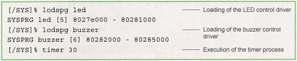
lodspg led
lodspg buzzer
timer 30
Motor control device driver
Make method
cd driver/motor/tbmx1
gmake
Load method
lodspg motor
Because the driver just simply resides
please combine it with the motor control application,
for example, to confirm operation.
Furthermore, motor externally attached hardware is necessary.
Motor control application (T-Kernel base)
Make method
cd kappl/disc/tbmx1
gmake
Execution method
Please execute after having first loaded the LED control device driver
and the motor control driver.
Furthermore, a motor and infrared sensor external hardware are
necessary.
lodspg led
lodspg motor
lodspg disc
Simple Web server (process base)
Make method
cd bappl/https/tbmx1
gmake
Execution method
In a case where you have placed an image file on the startup disk:
https
In a case where you have placed an image file on a FAT formatted SD
card:
https pcb0
Simple Web server test version (process base)
Make method
cd bappl/httptest/tbmx1
gmake
Execution method
httptest
|
____________________
[Note 1] In this article we are explaining the latest information on Teaboard, which at the time the article was written is a product in development. Because there may also be cases where a portion of the specifications and so on are modified in the product that is finally put on sale, please be understanding beforehand. Please confirm the latest information at the time you purchase Teaboard.
[Note 2] GPIO is an abbreviation of General Purpose Input/Output, and it is a function that carries out general-purpose digital input and output. Concerning the details of GPIO, please refer to "Motor Control through Teaboard."
The above article on Teaboard appeared on pages 46-56 in Vol. 95 of TRONWARE. It was translated and loaded onto this Web page with the permission of Personal Media Corporation.
Copyright © 2005 Personal Media Corporation
Copyright © 2009 Sakamura Laboratory, University Museum, University of Tokyo