
Because Teaboard possesses GPIO (General Purpose Input/Output) for digital input/output with external hardware, you can immediately use it also for control ports for various types of hardware. Accordingly, in this article, we will take up motor control based on infrared sensors as an example of hardware control using Teaboard.
 |
|
|
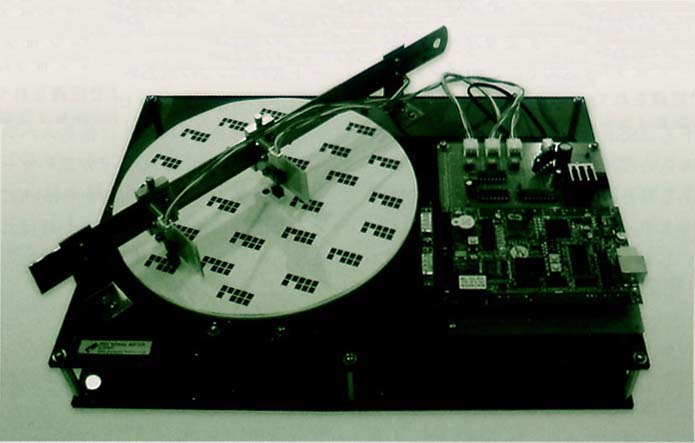
We show in Fig. 1 the overall image of the hardware we will fabricate. By means of a motor, we will make a disk revolve. On top of the disk, black marks are drawn, and we will read in those marks with infrared sensors. We will employ Teaboard for use in controlling the input from the sensors and the output to the motor. By counting inputs from the sensors, we will make it so that based on those values we can change the revolution speed and revolution direction of the motor and make it do various movements.
On the MC9328MX1, which is the CPU of Teaboard/ARM920-MX1, four GPIO ports (ports A ~ D) and a total of 110 pins appear. On Teaboard, several among these are connected to things such as switches and the RS-232C on the board, but because the remainder of these appear as I/O terminals, they can be freely employed for control use of externally connected hardware.
 |
|
|
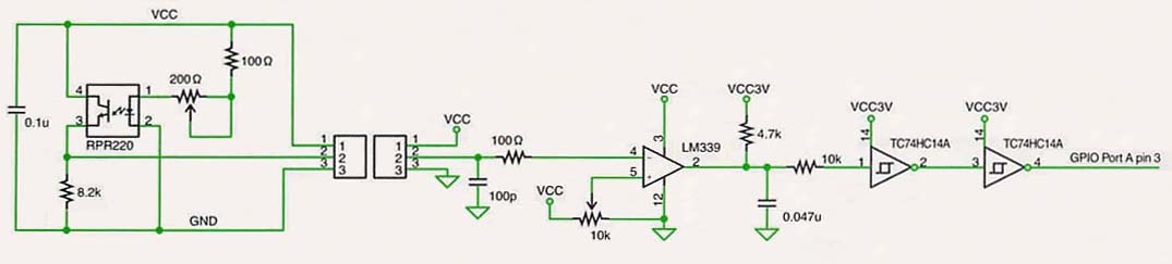
Here, we will make it our business to use pin 3 of GPIO Port A as an input from the infrared sensors. We show in Fig. 2 the circuit diagram. As for the infrared sensors, we use the we use a reflector-type photointerruptor (RPR220) in which an infrared emitter and receiver are made into one. When a black mark is placed in front of the sensor, infrared is absorbed without being reflected, and high is input into the GPIO.
|
|
||
| Address | Register Name | Meaning |
| 0x0021cP20 | GIUS_A ~ D (GPIO In Use Register) | 1: use as GPIO, 0: use as other function |
| 0x0021cP38 | GPR_A ~ D (General Purpose Register) | (function selection when using as other function) |
| 0x0021cP00 | DDIR_A ~ D (Data Direction Register) | Fixing of data direction (0: input, 1: output) |
| 0x0021cP24 | SSR_A ~ D (Sample Status Register) | Input data value |
| 0x0021cP1c | DR_A ~ D (Data Register) | Output data value |
In reading in pin input to the GPIO with software, we operate each register of the GPIO (Table 1). First, we write in 1 in bit 3 of the GIUS_A register, and then we make a setting so that we use that pin as the GPIO. Next, we write in 0 in bit 3 of the DDIR_A register, and then we set the data direction of this pin to input. If the program reads in bit 3 of SSR_A based on the above settings, in a case where a black mark appears in front of the sensor it becomes 1, and in a case where that is not so, it becomes 0.
However, by continuously monitoring the SSR_A register with a busy loop in software at all times, overall system real-time performance ends up getting degraded. Accordingly, here, instead of that, let's make a setting so that an interrupt is generated every time the sensor reads in a black mark. The interrupt vector number of pin 3 of GPIO Port A is defined with the macro IV_GPA(3). If we define the interrupt header in the manner of List 1, the sensor reads in the black mark, and the interrupt handler is called up in the instant that the pin moves from low to high.
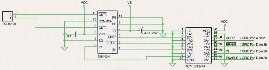
For control use of the direct-current motor that rotates the disk, we will make it our business to use the TA8440H IC here. This IC can freely control a direct-current motor with four signal wires: enable signal, forward/reverse signal, brake signal, chop signal. We connect these four signal wires to pins 28, 29, an 30 of GPIO Port D, and to pin 2 of GPIO Port A (Fig. 3).
 |
|
|
In controlling these signal wires with software, first, we set the GIUS register compatible bit to 1 and make it so that we use that pin as GPIO; and, next, we set the DDIR register compatible bit to 1 and make it so that we use that pin as output. Later, by means of writing into the bit compatible with DR register, we can control that signal wire. If we make the enable signal 1, the brake signal 1 (no brake), and the chop signal 1 (electric current on), the motor revolves at full speed, and we can change the direction of revolution by means of the forward and reverse signals.
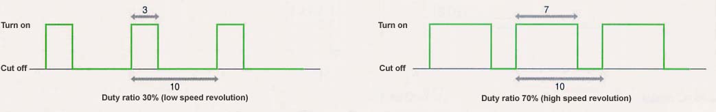
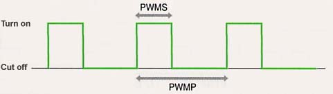
In that case, what should we do to change the revolution speed of the motor? The method that immediately comes to mind is changing the voltage by using a resistor, but because this generates heat, the energy efficiency is bad, and, moreover, it also isn't suited to computer control. Accordingly, what is frequently used instead of that is the method called Pulse Width Modulation (PWM). By giving pulses to the motor and changing the pulse current-on time width and the pulse frequency ratio (the duty ratio), we can change the revolution speed of the motor even with the voltage fixed as is (Fig. 4).
 |
|
|
Here, because we have connected the chop signal to pin 2 of GPIO A, if we give a pulse here, we can change the revolution speed of the motor. However, alternately writing in in the GPIO 1 and 0 for each fixed interval and generating pulses with software is troublesome. However, fortuitously, as a Pulse Width Modulator (PWM) [Note 1] that automatically generates pulses is built into the MC9328MX1, which is the CPU of Teaboard, let's make it our business to use this function.
|
|
||
| Address | Register Name | Meaning |
| 0x00208000 | PWMC (PWM Control Register) | PWM setting (bit 4 = 1 : run, 0 : stop |
| 0x00208004 | PWMS (PWM Sample Register) | Pulse width setting |
| 0x00208008 | PWMP (PWM Period Register) | Pulse frequency setting |
We show in Table 2 the main registers of the PWM. First, by means of writing in 0 in the GIUS_A register and bit 2 of the GPR_A register, we set it so that we use this pin as PWM output, and not GPIO. Later, by setting bit 4 of the PWMC register to 1, we run the PWM, and by means of setting the pulse frequency in the PWMP register and the pulse width in the PWMS register, the duty ratio PWMS ÷ PWMP pulse is generated (Fig. 5).
 |
|
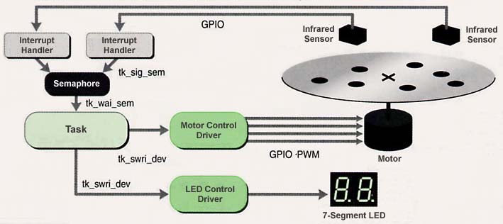
Because the outline of the sensor input part and the motor output part have been decided above, let's now decide to design the overall configuration of the software (Fig. 6).
 |
|
|
As for the overall software, we shall decide to create it on a T-Kernel base so that it can respond in real time to the reading of the marks by the sensor.
For the infrared sensors, we prepare two lines, and we connect them to pins 3 and 4 of GPIO Port A. When the sensor reads a black mark, an interrupt occurs, and the interrupt handler is started up.
That being the case, what would be the best way to notify the task from the interrupt handler that an interrupt has occurred? If we look at the T-Kernel specification, it looks like we could use APIs such as wake up task (tk_wup_tsk), increase semaphore value (tk_sig_sem), and set event flag (tk_set_flg). There are respective advantages, and whichever method you use is fine, but here we shall decide to use the semaphore.
 |
|
|
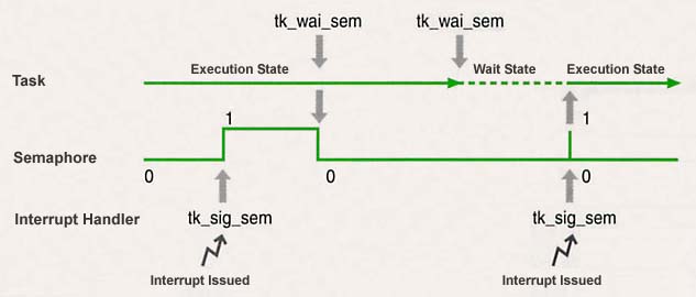
What we call a semaphore is an integer-type special variable that takes a nonnegative value, and it is the most popular method used for the purpose of synchronizing between a task and an interrupt handler or between a task and a task (Fig. 7). In T-Kernel, we can increase the value of a semaphore with tk_sig_sem. Also, with tk_wai_sem, we can reduce the value of a semaphore. However, in a case where the value of the semaphore is already zero, a task that has issued tk_wai_sem will enter the wait state until another task or interrupt handler issues tk_sig_sem [Note 2].
Accordingly, on the interrupt handler side we issue tk_sig_sem in regard to the semaphore. On the other hand, we detect this by means of tk_wai_sem in the task. After that, we shall decide to count up the counter that the task possesses internally, and then always display that number in the 7-segment LED using the LED control device driver. For the LED control device driver, we shall decide to use as is here also the one we created in the article "Program Development with Teaboard" (page 46 of this magazine). Furthermore, once the value of that counter has reached a certain value, we will issue an instruction to change the revolution speed and revolution direction of the motor in regard to the motor control device driver that we will describe below.
As for motor control, we shall decide to separate it from the main body of the application and make it into a single independent device driver. The merit of making it into a device driver is not just that operating tests as a single body of just this part become possible, rather there is also the point that it will come about that it can be used generically by calling it up even from other applications. Furthermore, if necessary, we can also distribute this device driver at the binary level. This is a great forte that is not possible but for T-Kernel, which facilitates the distribution of middleware.
|
|
|||||
|
"motor" | ||||
|
None | ||||
|
|
||||
We show in Table 3 the specification of this device driver. It is a simple driver with just a single attribute datum. When we call up this driver from an application and carry out write-in for this attribute datum, the driver side outputs the enable signal, the forward/reverse signal, and the brake signal to pins 28, 29, and 30 of GPIO Port D; and, moreover, using PWM, it outputs to the chop signal by generating specified duty ratio pulses.
We show the source code of this device driver in List 2. It is implemented using the Simple Device Driver Interface (SDI) layer. We carry out reading and writing in the GPIO and PWM registers using the I/O port access function. As the registers are all 32 bits in width, we use in_w() in reading-in, and out_w() in writing-in.
|
|
|
| Motor control device driver | driver/motor |
| LED control device driver | driver/led |
| Application main body | kappl/disc |
The source lists are all recorded in the CD-ROM attached to this issue. Please compile each of them, and then load them onto Teaboard with the lodspg command. It is necessary that the two device drivers are loaded in advance, prior to the execution of the main body of the application.
In this article, we introduced an example in which we control hardware using Teaboard. Using GPIO (General Purpose Input/Output), we carry out input and output, and we can also generate interrupts in response to inputs. As for outputs, not just the GPIO, but also PWM, which generates pulses, can also be used.
A great forte of Teaboard when compared to other boards is that T-Kernel, which is a standard real-time operating system for embedded use, can be used. If we use T-Kernel functions such as interrupts and task semaphores, high level real-time processing is possible with standardized techniques. Furthermore, by turning hardware control parts into device drivers, the distribution of highly generic modules becomes possible. By all means, please make use of Teaboard as a control board for self-made hardware.
____________________
| List 1 Interrupt Handler Definition Compatible with GPIO Port A Pin 3 |
T_DINT dint = { TA_HLNG, function pointer to interrupt handler};
tk_def_int( IV_GPA(3), &dint ) /* Interrupt handler definition */
SetIntMode( IV_GOA(3), IM_EDGE | IM_HI ); /* At the moment it changes
                       from high to low, it generates an interrupt */
ClearInt( IV_GPA(3) ) : /* Interrupt clear */
EnableInt( IV_GPA(3), 0 ); /* Interrupt permitted */
|
| List 2 Motor Control Device Driver Source Code |
/*
  Motor Control Device Driver
  Copyright (C) 2005 by Personal Media Corporation
 */

#include <tk/tkernel.h>
#include <device/sdrvif.h>

/* Data number definition */
enum {
  DN_MTMODE = -200 /* Attribute data number of mode setting */
};

/* Data structure definition */
typedef struct {
  unsigned int enable  :1; /* 0: stop, 1: rotate */
  unsigned int reverse :1; /* 0: forward, 1: back */
  unsigned int brake   :1; /* 0: no brake, 1: brake */
  unsigned int duty    :7; /* duty cycle (0 ~ 100%) */
} MtMode;

static MtMode datMode; /* Save attribute data */

/* Motor control */
static void set_mode( MtMode *p )
{
#define PWMC   0x00208000 /* PWM Control Register */
#define PWMS   0x00208004 /* PWM Sample Register */
#define PWMP   0x00208008 /* PWM Period Register */
#define GIUS_A 0x0021c020 /* GPIO Port A GPIO In Use Register */
#define GPR_A  0x0021c038 /* GPIO Port A General Purpose Register */
#define GIUS_D 0x0021c320 /* GPIO Port D GPIO In Use Register */
#define DDIR_D 0x0021c300 /* GPIO Port D Data Direction Register */
#define DR_D   0x0021c31c /* GPIO Port D Data Register */

#define CHOP   (1 << 2)   /* GPIO Port A pin 2  : chop signal */
#define EN     (1 << 30)  /* GPIO Port D pin 30 : enable signal */
#define IN     (1 << 29)  /* GPIO Port D pin 29 : forward/back signal */
#define BRAKE  (1 << 28)  /* GPIO Port D pin 28 : brake */

  UINT imask;

  DI( imask ); /* External interrupt prohibited */

  out_w( GIUS_D, in_w( GIUS_D ) | EN | IN | BRAKE ); /* Use GPIO as pin */
  out_w( DDIR_D, in_w( DDIR_D ) | EN | IN | BRAKE ); /* Output signal direction */
  out_w( DR_D, (in_w( DR_D ) & ~(EN | IN | BRAKE))
	 | (p -> enable  ? EN : 0)
	 | (p -> reverse ? IN : 0)
	 | (p -> brake   ? 0 : BRAKE) ); /* Output signal */

  out_w( GIUS_A, in_w( GIUS_A ) & ~CHOP ); /* Use pin as PWM */
  out_w( GPR_A, in_w( GPR_A ) & ~CHOP );
  out_w( PWMC,  (1 << 4) ); /* Set PWM to enable */
  out_w( PWMP, 0xfffe ); /* Set frequency */
  out_w( PWMS, (100 - (p -> duty)) * 0xffff / 100 ); /* Set duty cycle */

  datMode = *p; /* Save attribute data */

  EI( imask ); /* Permit external interrupt */
}
/*
 *   Read function: read-in processing
 */
static INT read_fn( ID devid, INT start, INT size, VP buf, SDI sdi )
{
  switch (start) {
  case DN_MTMODE:
    if (size >= sizeof(MtMode)) {
      *(MtMode*)buf = datMode;
      return sizeof(MtMode);
    }
  }
  return E_PAR;
}

/*
 *   Write function: write-in processing
 */
static INT write_fn( ID devid, INT start, INT size, VP buf, SDI sdi )
{
  switch (start) {
  case DN_MTMODE:
    if (size >= sizeof(MtMode)) {
      set_mode( (MtMode*)buf );
      return sizeof(MtMode);
    }
  }
  return E_PAR;
}

/*
 * Driver registration
 */
ER main( INT ac, UB *av[] )
{
  ER er;
  static SDI dsdi;
  static T_IDEV idev;
  static SDefDev ddev = {
    NULL,     /* Extension data */
    "motor",  /* Physical device name */
    0,        /* Driver attributes */
    0,        /* Device attributes */
    0,        /* Number of subunits */
    1,        /* Specific data block size */
    NULL,     /* Open function */
    NULL,     /* Close function */
    read_fn,  /* Read function */
    write_fn, /* Write function */
    NULL      /* Event function */
  };
  static MtMode imode = { 0, 0, 0, 0 }; /* Initial mode */

  if ( ac >= 0 ) { /* Time of loading */
    set_mode( &imode ); /* Initial mode setting */
    er = SDefDevice( &ddev, &idev, &dsdi ); /* Device registration */
  } else { /* Time of unloading */
    er = E_NOSPT; /* Device erasure not supported */
  }

  return ((er >= E_OK) ? E_OK : er);
}
|
| Makefile |
# # Motor Control Device Driver # Copyright (C) 2005 by Personal Media Corporation # # Source dependencies-related file (automatically generated) DEPS = Dependencies DEPENDENCIES_OUTPUT := $(DEPS) # Device driver standard rules include ../../etc/makerules # Creation target TARGET = motor # Path on which he source file exists VPATH = ../src # Source file SRC = motor.c OBJ = $(addsuffix .o, $(basename $(SRC))) CFLAGS += $(CFLAGS_WARNING) # ---------------------------------------------------------------------------- .PHONY: all clean all: $(TARGET) $(TARGET): $(OBJ) $(LINK.o) $(LDOBJS) $^ $(LOADLIBES) $(LDLIBS) $(OUTPUT_OPTION) $(STRIP) $@ clean: $(RM) $(OBJ) $(TARGET) $(DEPS) # Source dependencies-related ifdef DEPENDENCIES_OUTPUT $(DEPS): ; touch $(DEPS) else $(DEPS): $(SRC) ; $(MAKEDEPS) $@ $? endif include $(DEPS) |
| LED Control Device Driver |
/*
  LED Control Device Driver
  Copyright (C) 2005 by Personal Media Corporation
 */

#include <tk/tkernel.h>
#include <device/sdrvif.h>

/* Data number definitions */
enum{
  DN_LE8BIT  = -200,  /* 8-bit LED attribute data number */
  DN_LE7SEGR = -201,  /* Right 7-segment LED attribute data number */
  DN_LE7SEGL = -202,  /* Left 7-segment LED attribute data number */
  DN_LEDEC   = -203   /* 7-segment LED 2-figure attribute data number */
};

static int dat8BIT, dat7SEGR, dat7SEGL, datDEC; /* Saving of attribute data */

/* Display of 8-bit LED */
static void set8BIT( int x )
{
  out_h( 0x16100004, x ^ 0xff ); /* As 0 is ON, 1 is OFF, write in using bit inversion */
  dat8BIT = x; /* Save attribute data */
}

/* Display of right 7-segment LED */
static void set7SEGR( int x )
{
  out_h( 0x16100000, x ^ 0xff ); /* As 0 is ON, 1 is OFF, write in using bit inversion */
  dat7SEGR = x; /* Save attribute data */
}

/* Display of left 7-segment LED */
static void set7SEGL( int x )
{
  out_h( 0x16100002, x ^ 0xff ); /* As 0 is ON, 1 is OFF, write in using bit inversion */
  dat7SEGL = x; /* Save attribute data */
}

/* 7-segment LED 2-figure display */
static void setDEC( int x )
{
  /* +-a-+
     f   b  Correspondences of each segment and register bit
     +-g-+    bit7 = b, c, dot, d, e, g, f, a = bit0
     e   c
     +-d-+ dot */
  enum {b = 128, c = 64, dot = 32, d = 16, e = 8, g = 4, f = 2, a = 1};
  const unsigned char p[] = {
    a|b|c|d|e|f  , /* Pattern of 0 */
      b|c        , /* Pattern of 1 */
    a|b  |d|e  |g, /* Pattern of 2 */
    a|b|c|d    |g, /* Pattern of 3 */
      b|c|    f|g, /* Pattern of 4 */
    a  |c|d  |f|g, /* Pattern of 5 */
    a  |c|d|e|f|g, /* Pattern of 6 */
    a|b|c        , /* Pattern of 7 */
    a|b|c|d|e|f|g, /* Pattern of 8 */
    a|b|c|d  |f|g  /* Pattern of 9 */
  };

  set7SEGR( (x >= 0) ? p[x % 10] : (x >= -9) ? p[-x] : 0 ); /* Position of 1 */
  set7SEGL( (x >= 10) ? p[(x / 10) % 10] : (x >= 0) ? 0 : (x >= -9) ? g : 0 ); /* Position of 10 */
  datDEC = x; /* Save attribute data */
}

/*
 * Read function: read-in processing
 */
static INT read_fn( ID devid, INT start, INT size, VP buf, SDI sdi )
{
  switch (start) {
  case DN_LE8BIT:
    if (size >= 1) { *(UB*)buf = dat8BIT; return 1; }
  case DN_LE7SEGR:
    if (size >= 1) { *(UB*)buf = dat7SEGR; return 1; }
  case DN_LE7SEGL:
    if (size >= 1) { *(UB*)buf = dat7SEGL; return 1; }
  case DN_LEDEC:
    if (size >= 1) { *(B*)buf = datDEC; return 1; }
  }
  return E_PAR;
}

/*
 * Write function: write-in processing
 */
static INT write_fn( ID devid, INT start, INT size, VP buf, SDI sdi )
{
  switch (start) {
  case DN_LE8BIT:
    if (size >= 1) { set8BIT( *(UB*)buf ); return 1; }
  case DN_LE7SEGR:
    if (size >= 1) { set7SEGR( *(UB*)buf ); return 1; }
  case DN_LE7SEGL:
    if (size >= 1) { set7SEGL( *(UB*)buf ); return 1; }
  case DN_LEDEC:
    if (size >= 1) { setDEC( *(B*)buf ); return 1; }
  }
  return E_PAR;
}

/*
 * Driver registration
 */
ER main( INT ac, UB *av[] )
{
  ER er;
  static SDI dsdi;
  static T_IDEV idev;
  static SDefDev ddev = {
    NULL,     /* Extension data */
    "led",    /* Physical device name */
    0,        /* Driver attributes */
    0,        /* Device attributes */
    0,        /* Number of subunits */
    1,        /* Specific data block size */
    NULL,     /* Open function */
    NULL,     /* Close function */
    read_fn,  /* Read function */
    write_fn, /* Write function */
    NULL      /* Event function */
  };

  if ( ac >= 0 ) { /* Time of loading */
    setDEC( -10 ); set8BIT( 0 ); /* LED all extinguished */
    er = SDefDevice( &ddev, &idev, &dsdi ); /* Device registration */
  } else { /* Time of unloading */
    er = E_NOSPT; /* Device erasure not supported */
  }

  return ((er >= E_OK) ? E_OK : er);
}
|
| Makefile for LED Control Device Driver |
# # LED Control Device Driver # Copyright (C) 2005 by Personal Media Corporation # # Source dependencies-related file (automatically generated) DEPS = Dependencies DEPENDENCIES_OUTPUT := $(DEPS) # Device driver standard rules include ../../etc/makerules # Creation target TARGET = led # Path on which the source file exists VPATH = ../src # Source file SRC = led.c OBJ = $(addsuffix .o, $(basename $(SRC))) CFLAGS += $(CFLAGS_WARNING) # ---------------------------------------------------------------------------- .PHONY: all clean all: $(TARGET) $(TARGET): $(OBJ) $(LINK.o) $(LDOBJS) $^ $(LOADLIBES) $(LDLIBS) $(OUTPUT_OPTION) $(STRIP) $@ clean: $(RM) $(OBJ) $(TARGET) $(DEPS) # Source dependencies-related ifdef DEPENDENCIES_OUTPUT $(DEPS): ; touch $(DEPS) else $(DEPS): $(SRC) ; $(MAKEDEPS) $@ $? endif include $(DEPS) |
| Kappl/disc |
/*
  Disk (Motor + Infrared Sensor) Control Using Teaboard
  Copyright (C) 2005 by Personal Media Corporation
 */

#include <tk/tkernel.h>

/* Motor control driver : data number definition */
enum {
  DN_MTMODE = -200 /* Attribute data number of mode setting */
};

/* Motor control driver : data structure definition */
typedef struct {
  unsigned int enable  :1; /* 0: stop, 1: rotate */
  unsigned int reverse :1; /* 0: forward, 1: back */
  unsigned int brake   :1; /* 0: no brake, 1: brake */
  unsigned int duty    :7; /* duty cycle (0 ~ 100%) */
} MtMode;

/* LED control driver : data number definitions */
enum{
  DN_LE8BIT  = -200,  /* 8-bit LED attribute data number */
  DN_LE7SEGR = -201,  /* Right 7-segment LED attribute data number */
  DN_LE7SEGL = -202,  /* Left 7-segment LED attribute data number */
  DN_LEDEC   = -203   /* 7-segment LED 2-figure attribute data number */
};

#define SENSOR1 3 /* Infrared sensor 1 : GPIO Port A pin 3 */
#define SENSOR2 4 /* Infrared sensor 2 : GPIO Port A pin 4 */

volatile ID tid1; /* Task ID */
volatile ID semid1; /* Semaphore ID */

/* Interrupt handler for input from sensor 1 */
static void handler_sensor1( UINT dintno, VP sp )
{
  ClearInt( dintno );  /* Clear interrupt */
  tk_sig_sem( semid1, 1 ); /* Make semaphore value +1 */
}

/* Interrupt handler for input from sensor 2 */
static void handler_sensor2( UINT dintno, VP sp )
{
  ClearInt( dintno );  /* Clear interrupt */
  tk_sig_sem( semid1, 1 ); /* Make semaphore value +1 */
}

/* Motor control */
static void drive_motor( int dd, int duty, int reverse )
{
  MtMode m;
  int asiz;
  m.enable = 1;        /* 1: rotate */
  m.reverse = reverse; /* 0: forward, 1: back */
  m.brake = 0;         /* 0: no brake */
  m.duty = duty;       /* Duty cycle (0 ~ 100%) */
  tk_swri_dev( dd, DN_MTMODE, &m, sizeof(m), &asiz ); /* Write into motor control driver */
}

/* Task */
static void task1( INT stacd )
{
  static int duty[4] = { 10, 5, 10, 5 };
  static int reverse[4] = { 0, 0, 1, 1 };
  int mode = 0;
  char ct = 0;
  ID ddm, ddl; /* Device descriptor */
  ER er, asiz;

  ddm = tk_opn_dev( "motor", TD_UPDATE ); /* Open motor control driver */
  ddl = tk_opn_dev( "led", TD_UPDATE ); /* Open LED control driver */

  drive_motor( ddm, duty[mode], reverse[mode] ); /* Motor control */

  for(;;) {
    tk_swri_dev( ddl, DN_LEDEC, &ct, sizeof(ct), &asiz ); /* Display decimal count in 7-segment LED */
    er = tk_wai_sem( semid1, 1, TMO_FEVR ); /* Wait semaphore */
    if (er < 0) break; /* Terminate */

    ct++;
    if (ct >= 100) { /* When count value reaches 100, move to next mode */
      ct = 0;
      mode++;
      if (mode >= 4) mode = 0;
      drive_motor( ddm, duty[mode], reverse[mode] ); /* Motor control */
    }
  }

  /* Termination processing */
  tk_cls_dev( ddm, 0 ); /* Close motor control driver */
  tk_cls_dev( ddl, 0 ); /* Close LED control driver */
  tk_exd_tsk(); /* Terminate task, delete */
}

/* Initial settings */
static void init( void )
{
#define DDIR_A 0x0021c000 /* GPIO Port A Data Direction Register */
#define GIUS_A 0x0021c020 /* GPIO Port A GPIO In Use Register */

  UINT imask;
  static T_CTSK ctsk1 = { NULL, TA_HLNG | TA_RNG0, task1, 140, 0x1000 };
  static T_DINT dint1 = { TA_HLNG, handler_sensor1 };
  static T_DINT dint2 = { TA_HLNG, handler_sensor2 };
  static T_CSEM csem1 = { NULL, TA_TFIFO | TA_FIRST, 0, 99 };

  /* Create semaphore */
  semid1 = tk_cre_sem( &csem1 );

  DI(imask); /* Prohibit all interrupts */

  /* GPIO Port A Settings */
  out_w( GIUS_A, in_w( DDIR_A ) | (1 << SENSOR1) | (1 << SENSOR2) ); /* Use pin as GPIO */
  out_w( DDIR_A, in_w( GIUS_A ) & ~((1 << SENSOR1) | (1 << SENSOR2)) ); /* Set signal direction to input */

  /* Define interrupt handler for sensor input */
  tk_def_int( IV_GPA( SENSOR1 ), &dint1 );
  SetIntMode( IV_GPA( SENSOR1 ), IM_EDGE | IM_HI );
  ClearInt( IV_GPA( SENSOR1 ) );
  EnableInt( IV_GPA( SENSOR1 ), 0 );

  tk_def_int( IV_GPA( SENSOR2 ), &dint2 );
  SetIntMode( IV_GPA( SENSOR2 ), IM_EDGE | IM_HI );
  ClearInt( IV_GPA( SENSOR2 ) );
  EnableInt( IV_GPA( SENSOR2 ), 0 );

  EI( imask ); /* Release prohibition of all interrupts */

  /* Task startup */
  tid1 = tk_cre_tsk( &ctsk1 ); tk_sta_tsk( tid1, 0 );
}

/* Termination processing */
static void finish( void )
{
  /* Task termination */
  while( tk_dis_wai( tid1, TTW_SEM ) >= 0) {
    tk_dly_tsk( 10 );
  }

  /* Interrupt handler release */
  DisableInt( IV_GPA( SENSOR1 ) );
  tk_def_int( IV_GPA( SENSOR1 ), NULL );
  DisableInt( IV_GPA( SENSOR2 ) );
  tk_def_int( IV_GPA( SENSOR2 ), NULL );
  /* Semaphore deletion */
  tk_del_sem( semid1 );
}

/* Main */
ER main( INT ac, UB *av[] )
{
  if ( ac >= 0 ) { /* Time of loading */
    init(); /* Initial settings */
  } else { /* Time of unloading */
    finish();
  }
  return E_OK;
}
|
| Makefile |
# # Disk (Motor + Infrared Sensor) Control Using Teaboard # Copyright (C) 2005 by Personal Media Corporation # # Source dependencies-related file (automatically generated) DEPS = Dependencies DEPENDENCIES_OUTPUT := $(DEPS) # T-Kernel base standard rules include ../../etc/makerules # Creation target TARGET = disc # Path on which source file exists VPATH = ../src # Source file SRC = disc.c OBJ = $(addsuffix .o, $(basename $(SRC))) CFLAGS += $(CFLAGS_WARNING) #----------------------------------------------------------------------------- .PHONY: all clean all: $(TARGET) $(TARGET): $(OBJ) $(LINK.o) $(LDOBJS) $^ $(LOADLIBES) $(LDLIBS) $(OUTPUT_OPTION) $(STRIP) $@ clean: $(RM) $(OBJ) $(TARGET) $(DEPS) # Source dependencies-related ifdef DEPENDENCIES_OUTPUT $(DEPS): ; touch $(DEPS) else $(DEPS): $(SRC) ; $(MAKEDEPS) $@ $? endif include $(DEPS) |
|
|
This program collection is organized based on the latest information on
Teaboard, which is a product under development at the time of the writing
of this article. There is the possibility that some changes will be
needed for use in the product that is finally put on sale.

Organization of the Directory

 Process base programs

 bappl --+- https     Simple Web server
         |
         +- httptest  Simple Web server test version
         |
         +- timer     Timer

 Device drivers

 driver -+- buzzer    Buzzer control device driver
         |
         +- led       LED control device driver
         |
         +- motor     Motor control device driver

 T-Kernel base programs

 kappl --+- disc      Motor control application
         |
         +- roulette  Roulette

Make/Execution Methods

With reference to the examples below, perform make in the development
environment, and then execute on top of Teaboard.

Furthermore, for details, please refer to the text of the articles
published in TRONWARE Vol.95.

Roulette (T-Kernel base)

  Make method

  cd kappl/roulette/tbmx1
  gmake

  Execution method

  lodspg roulette

  When you press on the right push switch, you can start and stop
  the roulette revolution.

  When you press on the left push switch, roulette terminates.

Buzzer control device driver

  Make method

  cd driver/buzzer/tbmx1
  gmake

  Load method

  lodspg buzzer

  Because the driver just simply resides,
  please combine it with the timer program,
  for example, to confirm operation.

LED control device driver

  Make method

  cd driver/led/tbmx1
  gmake

  Load method

  lodspg led

  Because the driver just simply resides,
  please combine it with the timer program,
  for example, to confirm operation.

Timer (process base)

  Make method

  cd bappl/timer/tbmx1
  gmake

  Execution method

  Please execute after having first loaded the LED control device driver
  and buzzer control driver.

  lodspg led
  lodspg buzzer
  timer 30

Motor control device driver

  Make method

  cd driver/motor/tbmx1
  gmake

  Load method

  lodspg motor

  Because the driver just simply resides
  please combine it with the motor control application,
  for example, to confirm operation.
  Furthermore, motor externally attached hardware is necessary.

Motor control application (T-Kernel base)

  Make method

  cd kappl/disc/tbmx1
  gmake

  Execution method

  Please execute after having first loaded the LED control device driver
  and the motor control driver.
  Furthermore, a motor and infrared sensor external hardware are
  necessary.

  lodspg led
  lodspg motor
  lodspg disc

Simple Web server (process base)

  Make method

  cd bappl/https/tbmx1
  gmake

  Execution method

  In a case where you have placed an image file on the startup disk:

    https

  In a case where you have placed an image file on a FAT formatted SD
  card:

    https pcb0

Simple Web server test version (process base)

  Make method

  cd bappl/httptest/tbmx1
  gmake

  Execution method

  httptest
|
____________________
[Note 1] PWM is used as an abbreviation for both "pulse width modulation" and the "circuits on which we make that occur."
[Note 2] In T-Kernel, the range of increase and decrease in semaphore values can be arbitrarily specified, but, here, we have explained in the case of ± 1.
The above article on Teaboard appeared on pages 57-62 in Vol. 95 of TRONWARE. It was translated and loaded onto this Web page with the permission of Personal Media Corporation.
Copyright © 2005 Personal Media Corporation
Copyright © 2009 Sakamura Laboratory, University Museum, University of Tokyo